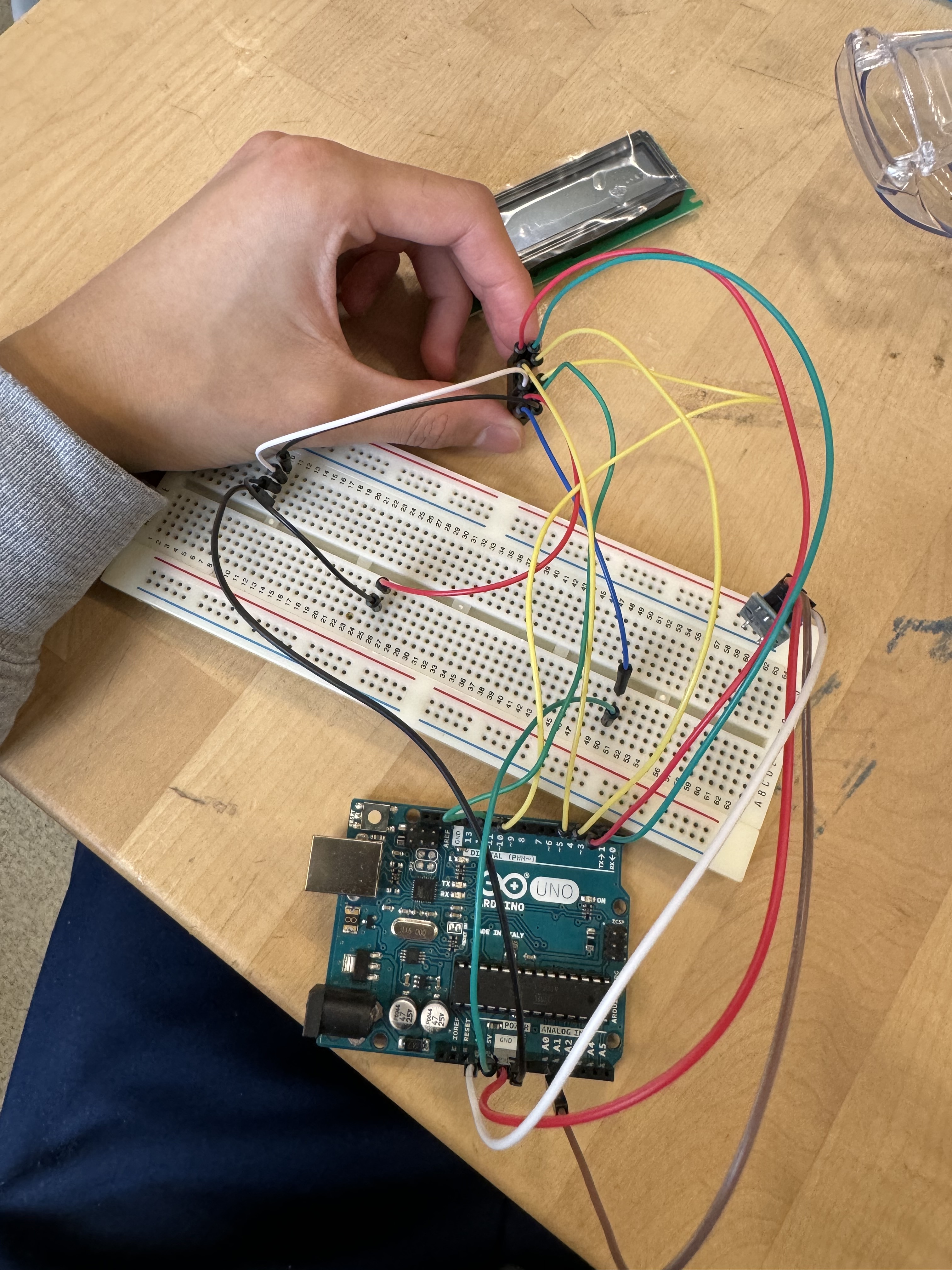
Hi, I'm currently working on a project related to LCDs. I want the LCD to display a message if enough current is inputted. But, when I assembled it I think I wired my LCD wrong. Is it possible to check where I went wrong?
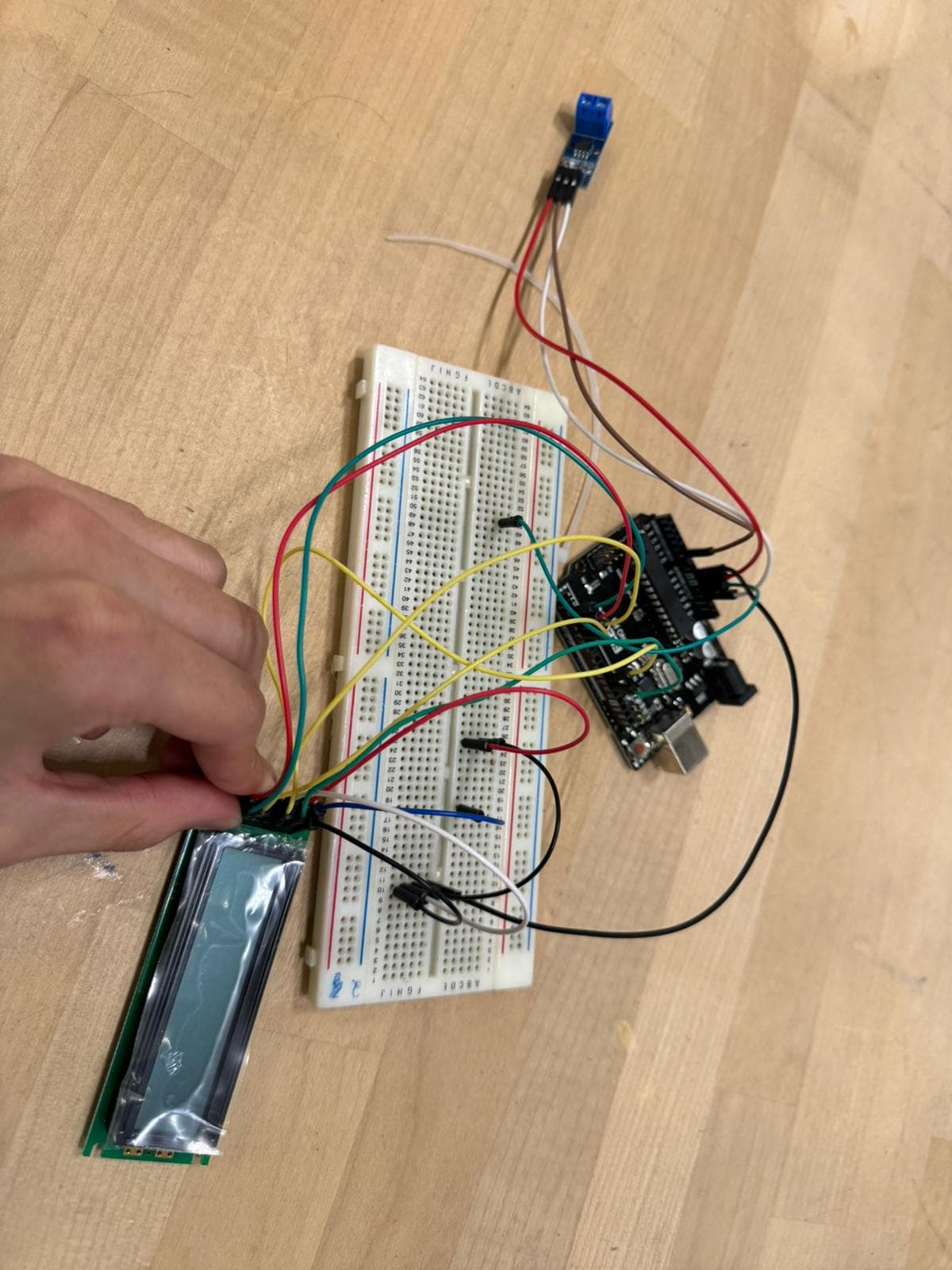
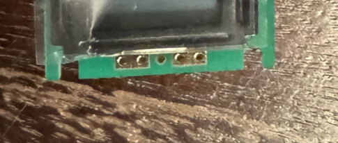
Here is what the LCD looks like when it is connected to the circuit:
The wire on the 1st Column 6th Row: Vss
The wire on the 2nd Column 6th Row: Vdd
The wire on the 1st Column 5th Row: RS
The wire on the 2nd Column 5th Row: V0
The wire on the 1st Column 4th Row: R/W
The wire on the 1st Column 4th Row: E
The wire on the 2nd Column 2nd Row: DB5
The wire on the 1st Column 2nd Row: DB4
The wire on the 2ndColumn 1st Row: DB6
The wire on the 1st Column 6th Row: DB7
The wire on the 2nd Column 1st Row: Vss
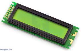
But I don't know where else I can get the same one. It might be a LCD that is only produced in this shop. It just says LCD character display module 16 x 2 backlit
2. From figure of post #1, it looks like that you have already soldered female header on the empty holes of the Header. Now, consult Fig-1 and make conection between lCD and Arduino UNO. You need to feed 5V supply with a series resistor for te back light ofthe LCD.
The connection isn't soldered yet cause I want to make sure the wiring is connect before I solder the wires to the LCD.
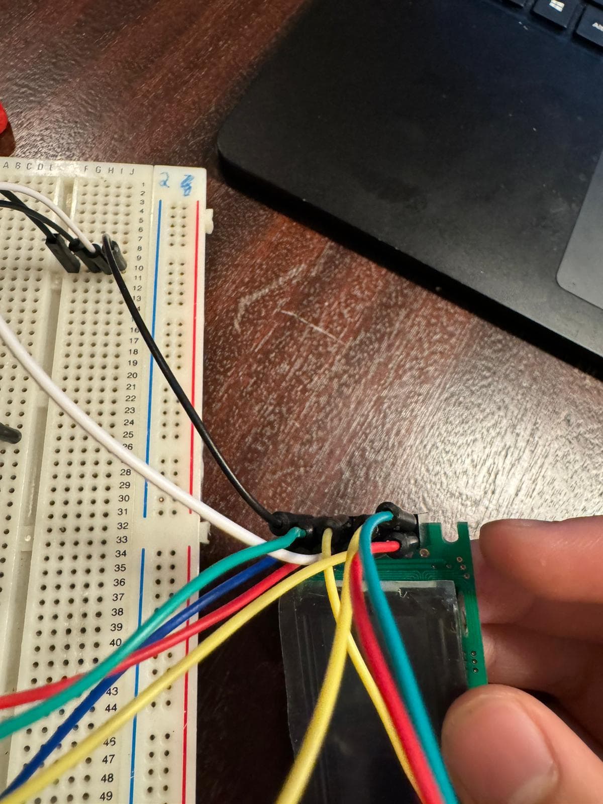
Here is also a better picture of the wiring. I'm really sorry that I didn't make it clear enough when I took the original photo.
Thank you so much! I can see the pins much better. I'll made the connection with the arduino and the LCD lights up but its overheating now. So I'm considering adding a resistor but where in the circuit should I put the resistor?
You mean the female headers ? It needs to be soldered for the LCD to work. There is high frequency communication happening on those pins and the connection needs to be good.
If it’s warm it mightmeans you need to limit the backlight current - add a resistor there
The blue squares might just be the need for a contrast potentiometer somewhere to be either added or just tuned if it’s already there
I am currently working on the soldering. But I am not sure where to put a contrast potentiometer if I am going to acquire it. Should I connect it with VSS, VDD, V0, and R/W?
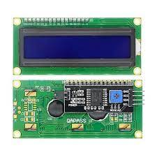
Thank you so much! I think I understand it better now but I am confused why there are 16 pins on the LCD. My one only has 14 so should I bypass the connection with LED- and LED+? The one I have is pointed out by @GolamMostafa
are those pins on the other side connected to anything ?
the Chinese text mentions a LED with a forward voltage of 4.2V and at the bottom they mention 10Ω to 100Ω... would be good to understand exactly what that text means
I will also show the code which I am using to see if the LCD displays anything. Its:
#include <LiquidCrystal_I2C.h>

LiquidCrystal_I2C lcd(0x3F,16,2);  // set the LCD address to 0x3F for a 16 chars and 2 line display

void setup()
{
  lcd.init();
  lcd.clear();
  lcd.backlight();      // Make sure backlight is on

  // Print a message on both lines of the LCD.
  lcd.setCursor(2,0);   //Set cursor to character 2 on line 0
  lcd.print("Please input");

  lcd.setCursor(2,1);   //Move cursor to character 2 on line 1
  lcd.print("Current");
}

void loop()
{
    lcd.init();
    lcd.clear();
    lcd.backlight();      // Make sure backlight is on

    lcd.setCursor(2,0);   //Set cursor to character 2 on line 0
    lcd.print("High Score:");

    lcd.setCursor(2,1);   //Move cursor to character 2 on line 1
    lcd.print("0000");
        }
➜ You don't have an I2C LCD. you can't use that code to initialise the LCD. instance
refer to the tutorial I pointed out earlier, you'll see they do something like this with the LiquidCrystal library not the LiquidCrystal_I2C one.
// include the library code:
#include <LiquidCrystal.h>

// initialize the library by associating any needed LCD interface pin
// with the arduino pin number it is connected to
const int rs = 12, en = 11, d4 = 5, d5 = 4, d6 = 3, d7 = 2;
LiquidCrystal lcd(rs, en, d4, d5, d6, d7);
use a couple resistors. You won't be able to change the voltage but at least you could "simulate" a potentiometer set at a given point
Thank you very much!!! I’ll change the code right now. As for resistors I have 100R and 330 R I’ll see how I can connect it on the bread board. Thank you!
1. You may follow this diagram (Fig-1) to make connection between LCD and UNO. If you don't have a potentiometer (R1 in Fig-1) for the contrast adjustment, then you may try with a fixed valued resistor (1.5k or 2k) instead.