Hello everyone! I have a problem with a MAX7219 and 4 digits 7 segments. For example when I want to display a "1" it shows me a "3" in reverse, everything is reversed, the LEDs are turned "on" when they should be "off" and are "off" when they should be "on"! Also, when I use more than one digit, there is a problem of scans, while the digit is "fuzzy".
What I do not understand is that there is one month, I managed to do everything worked the first time! I tried everything, I do not know what I had done over the first time: | .
-The wiring is good.
-The scketch is good too!
-with an oscilloscope, the bits correspond to what I mailings.
tonytony72:
-The wiring is good.
-The scketch is good too!
Well, that's what you say, but I bet one or the other is wrong. I suppose there might even be a faint possibility that youi are using a common anode 4x7, but we'll will never know until you reveal your code and wiring.
If you find it hard to be forthcoming, you might find some useful stuff here first.
SPI.begin ();
sendByte (MAX7219_REG_SCANLIMIT, 3); // show 4 digits
sendByte (MAX7219_REG_DECODEMODE, 0xFF); // use digits (not bit patterns)
sendByte (MAX7219_REG_DISPLAYTEST, 0); // no display test
sendByte (MAX7219_REG_INTENSITY, 7); // character intensity: range: 0 to 15
sendByte (MAX7219_REG_SHUTDOWN, 1); // not in shutdown mode (ie. start it up)
}
it should be displayed "1234" but ilisible. and if I replace "sendByte (MAX7219_REG_SCANLIMIT 3)" by "sendByte (MAX7219_REG_SCANLIMIT, 0)" to display the first digit, it displays "x333" in place of "1xxx"
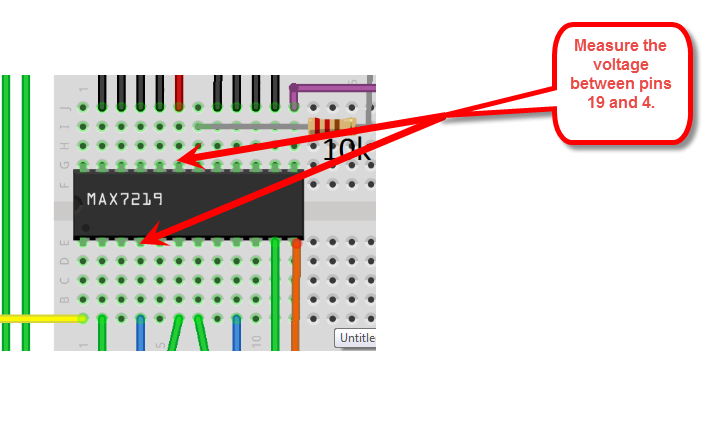
Here is my wiring. Top right I drew what I get when I want to display "1234" (Red = "on", black = "off"). I tested SEVERAL MAX7219. I also tried without the 10k resistor between vcc and Iset
Here is my display (5v on digits, gnd on segments). For capacitors, I half as in the diagram but in reality they are directly on the gnd and vcc pin of the MAX7219 without wires.
between pins 19 and 4 I 4.60v.
Another strange thing:
"sendByte (MAX7219_REG_INTENSITY, 7);" <== When the value is "1", the lighting is high and when the value is "15", the lighting is very low, while it should be the opposite!
There really is something that reads everything upside down! As if the bits arduino sends a MAX7219 was reversed. But the oscilloscope it is correct.
the common cathode is for 5v and gnd on the anodes? For me I think I have the right display. and in case I tried with a common anode display and it does not work at all.
And I had already managed to run the scketch with exactly the same material (I really do not understand!)
Move your +5 and GND wires (the ones from the arduino) to the far left side of your breadboard power buses.
Some bread boards have a break half way down the power rails.
It might be your grounds aren't really there because of the above situation.
the common cathode is for 5v and gnd on the anodes?
No.
The DIGIT pins connect to the cathode pins and pull them low 1 at a time.
The SEGMENT pins connect to the anode pins and drive them high in groups to make up the fonts you see.
I'm really stupid stupid STUPIDDDDDDDDDDDDD! You right CrossRoads. It is I who tangled brushes! I mixed the cathodes and anodes in the same box!! So first I have faith u lucky to come to the right display. Then when I tested a cathode with a display that was not working because in testes but apparently I should have blown a capacitor!
But now everything works! Thank you very much for your help and sorry for taking the time!
You're not the first to mix those up, nor will you be the last.
I have some 8x8 displays that I wired up, and it wasn't until I had the 16th wire done that I realized the parts had 24 pins and were actually two color displays. Hazards of late night design!