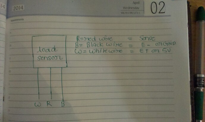
Hi , i am trying to use load sensor like this one Load Sensor - 50kg (Generic) - SEN-10245 - SparkFun Electronics. Basically what i had done, i had just dissected a personal weighing scale and removed the load sensor. But got no success in using them with Arduino. I am using INA125P instrumentation amplifier with below configuration. File enclosed with this question
Where S+ and S- are Sense + and Sense -. I tried all the configuration i.e single load cell, half wheat-stone bridge, full weat-stone bridge but nothing worked. I only keep on getting some random ADC value 14-16 and even on pressing the load sensor upside down, nothing changed. Basically i followed the below configuration while trying with single load cell.
I am trying to use a 3 wire load sensor, connect it to INA125 for voltage amplification and then use the amplified output to be fed to ADC of Arduino.
I had used below configuration with INA125. enter image description here
Where S+ and S- are Sense + and Sense -. I tried all the configuration i.e single load cell, half wheat-stone bridge, full weat-stone bridge but nothing worked. I only keep on getting some random ADC value 14-16 and even on pressing the load sensor upside down, nothing changed. Basically i followed the below configuration while trying with single load cell.
And a simple arduino code, just to read ADC value in order to check , whether i am getting things right. As per code, the ADC value must change, but they didn't. Below is the sample code.
#include<stdio.h>
#include <LiquidCrystal.h>
LiquidCrystal lcd(12, 11, 5, 4, 3, 2);

int sensorValue = 0;
int sensorPin = A0;


void setup()
{

  Serial.begin(9600);
  Serial.println("Weight sensor reading");
  lcd.begin(16, 2);

}

void loop()
{
  lcd.begin(16, 2);
  lcd.setCursor(0,0);
  lcd.print("Weight measurement");
  sensorValue = analogRead(sensorPin);
  Serial.print(sensorValue);
  lcd.setCursor(0,1);
  lcd.print(sensorValue);
  delay(200);
}
Now with respect to the single load cell, i connected black to GND, white to +5V and Red to S+ at pin 6 of INA125 and i connected PIN7 that is S- to GND. But this didn't worked.
When i used 2 load sensors, i connected the white wires of both load sensors to +5V, Black wire to GND, RED wire of 1st load sensor to S+ and RED wire of other load sensor to S-. But even that didn't work and readings remain same i.e. 14-16 volts and didn't change even on applying sufficient amount of pressure.
Now with respect to the full wheat-stone bridge configuration, i used this pic based configuration given on below link.But even it didn't worked
http://www.nerdkits.com/forum/thread/900/
I am not able to understand what i am doing wrong.Can any one suggest me
Important : I am using 10k resistance between PIN8 an PIN9, which provide me a gain of 10. Is that sufficient for arduino to read ? Or i must use some other resistance which must provide me a higher gain. But i think even with 10k resistance i must see some change in the value of the ADC, but i am not even getting that. In my earlier question also, i asked a similar type of question, but at that time i wasn't having INA125 with me.Link for the question is given below.
I had enclosed pic for the arrangement which i am using at present named as loadsensorreadings.jpg
Below is the pic for the configuration which i am using.
I had asked a detailed question at stackover flow and repeating that here too.
Earlier i had used 10k resistance for Rg and now with 60ohm but neither of them worked.


