Problems getting linear actuator with feedback pot to work

Hi, I am new to arduino, and I am trying to use a linear actuator with a built in pot have it's position controlled by a different linear pot. So moving the external pot should move the actuator to a corresponding position. The coding I am using is from Firgelli automation on their tutorial on how to do this. I have a BTS7960 IC high current dc motor driver to control the actuator, run by pin 9 and 10 on the pwm out. My question is, When I have the pot plugged in on it's own, in the serial monitor it shows the range as 0-1023 as I move it, as it should. But if I have the pot for the actuator, or "sensor" as this code refers to, it shows both readings as about 960 and the values do not change as I move the pot. Also, the serial monitor has a read function for "pot position" and "sensor position", and my understanding of the code is that the sensor position should show position of the actuator, and pot position should show position of the pot. However, If I plug the pot signal pin into either A0 or A1, it shows it under "sensor position" regardless of which pin it is plugged into, and pot position shows 0. I have tried reassigning pins to pins A1 and A2, and A2 and A3, and still the same problem. I did have a little bit of an arc issue where a wire for the ground touched the 12V supply. Could my board be toast? Or am I doing something wrong/is there something wrong with some of the code? I will attach a schematic of how it is wired and of the code.
Thanks in advance,
-Jared

/* Firgelli Automations
 * Limited or no support: we do not have the resources for Arduino code support
 * 
 * Program enables momentary direction control of actuator using push button
 */
 
#include <elapsedMillis.h>
elapsedMillis timeElapsed;

int RPWM = 10;   
int LPWM = 11;
int sensorPin = A0;
int potPin = A1;
int potVal;

int sensorVal;
int Speed = 255;
int Buffer = 4;

int maxAnalogReading;
int minAnalogReading;

void setup() {
  pinMode(RPWM, OUTPUT);
  pinMode(LPWM, OUTPUT);
  pinMode(sensorPin, INPUT);
  pinMode(potPin, INPUT);
  Serial.begin(9600);
  maxAnalogReading = moveToLimit(1);
  minAnalogReading = moveToLimit(-1);
}

void loop(){
  potVal = map(analogRead(potPin), 0, 1023, minAnalogReading, maxAnalogReading);
  sensorVal = analogRead(sensorPin);
  if(potVal > (sensorVal+Buffer)){               //addition gives buffer to prevent actuator from rapidly vibrating due to noisy data inputs
    driveActuator(1, Speed);
  }
  else if(potVal < (sensorVal-Buffer)){             
    driveActuator(-1, Speed);
  }
  else{
    driveActuator(0, Speed);
  }
  Serial.print("Potentiometer Reading: ");
  Serial.print(potVal);
  Serial.print("\tActuator reading: ");
  Serial.println(sensorVal);
  delay(10);
}

int moveToLimit(int Direction){
  int prevReading=0;
  int currReading=0;
  do{
    prevReading = currReading;
    driveActuator(Direction, Speed);
    timeElapsed = 0;
    while(timeElapsed < 200){ delay(1);}           //keep moving until analog reading remains the same for 200ms
    currReading = analogRead(sensorPin);
  }while(prevReading != currReading);
  return currReading;
}

void driveActuator(int Direction, int Speed){
  switch(Direction){
    case 1:       //extension
      analogWrite(RPWM, Speed);
      analogWrite(LPWM, 0);
      break;
   
    case 0:       //stopping
      analogWrite(RPWM, 0);
      analogWrite(LPWM, 0);
      break;

    case -1:      //retraction
      analogWrite(RPWM, 0);
      analogWrite(LPWM, Speed);
      break;
  }
}

IMG_0400

Hopefully that worked for the image of the drawing. How do I attach a JPEG?Preformatted text
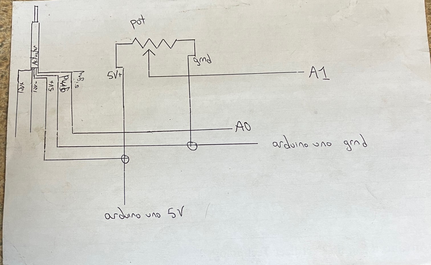
Thanks for posting a hand drawn schematic, but it is too small to see clearly. Please crop and repost a larger version.

The pot on the actuator has to be powered by the Arduino 5V (or whatever the selected AREF might be). Grounds must be common, as well.

How do I attach a JPEG?

Just drag the image into the post editor window.

A link to the data sheet were helpful.

Does this do anything? It should move the actuator to the limits.

As a check, Serial.print() the values that are returned. If they aren't sensible, the map() function below won't work properly.

The grounds are connected together and 5v power is supplied by the arduino. I don't have a schematic of the actuator, as it is a take-off of a piece of equipment of ours. Can I take some resistance measurements that might help you?
This code:

  maxAnalogReading = moveToLimit(1);
  minAnalogReading = moveToLimit(-1);

Moves that actuator all the way one direction, but that is all. I'm thinking that maybe it's the pot built into the actuator isn't showing that the actuator is actually moving?
Larger diagram attached here.

I think that is the problem. For the map function to work, you need to know the actuator pot reading at both limits of the motion.

Post a link to the actuator.

Also, in my experience with those actuators (I think the one I have here is from Progressive Automations), the feedback potentiometers tend to be fairly noisy so you should consider filtering the output.

What is the raw ADC reading from A0 when the actuator is fully retracted? When fully extended? When exactly half way?

analog "sensor value" goes from 690 fully extended to 146 fully retracted. I believe it is a 10k ohm resistor from my multimeter measurements. I don't have a link to the actuator, as it is just a part off of a combine (farm equipment). It does look like I will be buying one from elsewhere for my project though, so I will post those specs when I get to that point. Why would the actuator not be traveling to both limits? Is it because the pot readings aren't going all the way to 1023? Also, I tried having the pot pin for the "potentiometer reading" (A1) unhooked, and it is showing that pot reading as 146. Should there even be a reading when unhooked? It was unhooked when I started up the arduino, so I don't think it should be the last known reading or anything.

There are several possibilities. Among them, you may have wired the setup incorrectly, the motor driver is damaged, or the actuator is damaged.

Post a complete wiring diagram, including the motor driver, motor power supply and Arduino, specs of the motor power supply and a link to the motor driver data sheet.

analog "sensor value" goes from 690 fully extended to 146 fully retracted.

How did you get these values, if the actuator does not travel to both limits?

Perhaps the device was not made to travel from limit to limit. Did it actually move from limit to limit when used on the combine?

To get the values, I kept the pot portion of the actuator hooked into the arduino, and ran the actuator from limit to limit by hooking directly to 12v battery momentarily.
Update: I actually did get it all to work. I must not have had it hooked up exactly right. Although the serial print does not show the values for the pot to be moving from 0 to 1023 as they should, but that's fine, as I am just concerned with the physical functionality of the unit. So, it's working now! Thank you!

Two more questions here:

  1. Let's say I don't use all of the travel in my potentiometer (Lets say half of the travel), but I want that to correspond to full travel of the actuator. What do I change to code that?
  2. If I want to add a second actuator, and have that actuator run in inverse position of the pot, how would I add that into the code? So say max retract on pot means max extend on acuator.

I am surprised at this statement! What leads you to think the values should go from 0 to 1023? You have the actual values from the pot and can map them to 0 to 1023 if that is what you want. The physical construction of all potentiometers require a zero Ohm connection at the ends of the resistive element. Some have sliders that actually make contact with the end connection so the movement of the slider is limited so as to NOT contact the zero Ohm connection. That is why a 10k pot will not show zero ohms and will not show 10k. It may have an 11k Ohm element with limits at 100 ohms and 10k Ohms. But manufacturing of the devices will always be +- 10 to 20 percent.

Two more questions here:

  1. Choose the values for minAnalogReading and maxAnalogReading to match those at the desired travel limits:
    potVal = map(analogRead(potPin), 0, 1023, minAnalogReading, maxAnalogReading);

  2. I don't what you mean by "inverse position of the pot".

The pot on the actuator informs you of the current extension or position. Your program must make control decisions based on actual versus desired extension.

Sorry, by inverse position of the pot, what I mean is that right now, when the linear pot is extended all the way, the actuator is extended all the way. I want to run two actuators off of one pot, with actuator 1 extending when pot extends, and actuator 2 retracting when pot extends. Is this possible?

Yes, that is possible.

So I figured out how to make one actuator work as I want, and now I am trying to figure out how to drive two of the actuators off the same pot. The first set of code is the code I used from Firgelli Automation to control a linear actuator with a pot, and the second set of code is with me trying to make my own modifications to the code to make it so it drives a second actuator (designated by "left" throughout the code). The left actuator goes to its two limits as it should, and then back to the middle position, and does not move with the pot like the right one was. What am I missing?

[code]
/* Firgelli Automations
   Limited or no support: we do not have the resources for Arduino code support

   Program enables momentary direction control of actuator using push button
*/

#include <elapsedMillis.h>
elapsedMillis timeElapsed;

int RPWM = 10;
int LPWM = 11;
int sensorPin = A0;
int potPin = A1;
int potVal;

int sensorVal;
int Speed = 255;
int Buffer = 4;

int maxAnalogReading;
int minAnalogReading;

void setup() {
  pinMode(RPWM, OUTPUT);
  pinMode(LPWM, OUTPUT);
  pinMode(sensorPin, INPUT);
  pinMode(potPin, INPUT);
  Serial.begin(9600);
  maxAnalogReading = moveToLimit(1);
  minAnalogReading = moveToLimit(-1);
}

void loop() {
  potVal = map(analogRead(potPin), 0, 1023, minAnalogReading, maxAnalogReading);
  sensorVal = analogRead(sensorPin);
  if (potVal > (sensorVal + Buffer)) {           //addition gives buffer to prevent actuator from rapidly vibrating due to noisy data inputs
    driveActuator(1, Speed);
  }
  else if (potVal < (sensorVal - Buffer)) {
    driveActuator(-1, Speed);
  }
  else {
    driveActuator(0, Speed);
  }
  Serial.print("Potentiometer Reading: ");
  Serial.print(potVal);
  Serial.print("\tActuator reading: ");
  Serial.println(sensorVal);
  delay(10);
}

int moveToLimit(int Direction) {
  int prevReading = 0;
  int currReading = 0;
  do {
    prevReading = currReading;
    driveActuator(Direction, Speed);
    timeElapsed = 0;
    while (timeElapsed < 200) {
      delay(1); //keep moving until analog reading remains the same for 200ms
    }
    currReading = analogRead(sensorPin);
  } while (prevReading != currReading);
  return currReading;
}

void driveActuator(int Direction, int Speed) {
  switch (Direction) {
    case 1:       //extension
      analogWrite(RPWM, Speed);
      analogWrite(LPWM, 0);
      break;

    case 0:       //stopping
      analogWrite(RPWM, 0);
      analogWrite(LPWM, 0);
      break;

    case -1:      //retraction
      analogWrite(RPWM, 0);
      analogWrite(LPWM, Speed);
      break;
  }
}
[/code]

The code that I modified to try and run two actuators from one pot is as follows:

[code]
/* Firgelli Automations
   Limited or no support: we do not have the resources for Arduino code support

   Program enables momentary direction control of actuator using push button
*/

#include <elapsedMillis.h>
elapsedMillis timeElapsed;

int RPWMRight = 10;
int LPWMRight = 11;
int RPWMLeft = 6;
int LPWMLeft = 9;
int sensorPin = A0;
int potPin = A1;
int leftsensorPin = A4;
int potVal;
int leftpotVal;

int leftsensorVal;
int sensorVal;
int Speed = 255;
int Buffer = 4;

int maxAnalogReading;
int minAnalogReading;
int leftmaxAnalogReading;
int leftminAnalogReading;

void setup() {
  pinMode(RPWMRight, OUTPUT);
  pinMode(LPWMRight, OUTPUT);
  pinMode(RPWMLeft, OUTPUT);
  pinMode(LPWMLeft, OUTPUT);
  pinMode(sensorPin, INPUT);
  pinMode(potPin, INPUT);
  pinMode(leftsensorPin, INPUT);
  Serial.begin(9600);
  maxAnalogReading = moveToLimit(1);
  minAnalogReading = moveToLimit(-1);
  leftmaxAnalogReading = leftmoveToLimit(1);
  leftminAnalogReading = leftmoveToLimit(-1);
}

void loop() {
  potVal = map(analogRead(potPin), 0, 1023, minAnalogReading, maxAnalogReading);      //original mapping to be used with right actuator
  leftpotVal = map(analogRead(potPin), 0, 1023, minAnalogReading, maxAnalogReading);  //opposite direction mapping for left actuator
  sensorVal = analogRead(sensorPin);                                                //Right actuator reading
  leftsensorVal = analogRead(leftsensorPin);                                        //Left actuator reading
  if (potVal > (sensorVal + Buffer)) {           //addition gives buffer to prevent actuator from rapidly vibrating due to noisy data inputs
    driveActuator(1, Speed);
  }
  else if (potVal < (sensorVal - Buffer)) {
    driveActuator(-1, Speed);
  }
  else {
    driveActuator(0, Speed);
  }
  if (leftpotVal > (leftsensorVal + Buffer)) {           //addition gives buffer to prevent actuator from rapidly vibrating due to noisy data inputs
    leftdriveActuator(1, Speed);
  }
  else if (leftpotVal < (leftsensorVal - Buffer)) {
    leftdriveActuator(-1, Speed);
  }
  else {
    leftdriveActuator(0, Speed);

  }

  Serial.print("Potentiometer Reading: ");
  Serial.print(potVal);
  Serial.print("\tActuator reading: ");
  Serial.println(sensorVal);
  Serial.print("\tLeftActuator reading: ");
  Serial.println(leftsensorVal);
  Serial.print("\tLeft Pot Reading: ");
  Serial.println(leftpotVal);
  delay(10);
}

int moveToLimit(int Direction) {
  int prevReading = 0;
  int currReading = 0;
  do {
    prevReading = currReading;
    driveActuator(Direction, Speed);
    timeElapsed = 0;
    while (timeElapsed < 200) {
      delay(1); //keep moving until analog reading remains the same for 200ms
    }
    currReading = analogRead(sensorPin);
  } while (prevReading != currReading);
  return currReading;
}


void driveActuator(int Direction, int Speed) {
  switch (Direction) {
    case 1:       //extension
      analogWrite(RPWMRight, Speed);
      analogWrite(LPWMRight, 0);
      break;

    case 0:       //stopping
      analogWrite(RPWMRight, 0);
      analogWrite(LPWMRight, 0);
      break;

    case -1:      //retraction
      analogWrite(RPWMRight, 0);
      analogWrite(LPWMRight, Speed);
      break;
  }
}
int leftmoveToLimit(int Direction) {
  int prevReading = 0;
  int currReading = 0;
  do {
    prevReading = currReading;
    leftdriveActuator(Direction, Speed);
    timeElapsed = 0;
    while (timeElapsed < 200) {
      delay(1); //keep moving until analog reading remains the same for 200ms
    }
    currReading = analogRead(leftsensorPin);
  } while (prevReading != currReading);
  return currReading;
}

void leftdriveActuator(int Direction, int Speed) {
  switch (Direction) {
    case 1:       //extension
      analogWrite(RPWMLeft, Speed);
      analogWrite(LPWMLeft, 0);
      break;

    case 0:       //stopping
      analogWrite(RPWMLeft, 0);
      analogWrite(LPWMLeft, 0);
      break;

    case -1:      //retraction
      analogWrite(RPWMLeft, 0);
      analogWrite(LPWMLeft, Speed);
      break;
  }
}
[/code]

I have another, shorter question here. In the attached code, why is

[code]
int moveToLimit(int Direction) {
  int prevReading = 0;
  int currReading = 0;
  do {
    prevReading = currReading;
    driveActuator(Direction, Speed);
    timeElapsed = 0;
    while (timeElapsed < 200) {
      delay(1); //keep moving until analog reading remains the same for 200ms
    }
    currReading = analogRead(sensorPin);
  } while (prevReading != currReading);
  return currReading;
}

[/code]

in the void loop rather than void setup? It is intended to be the initial calibration of the electric actuator with built in sensor in this code (or at least so I understand). Shouldn't it be in the void setup section so that it only runs once at setup? This code does work, but I'm trying to understand why the original author placed it in the void loop part. Full original code as follows (not my code):

[code]
/* Firgelli Automations
   Limited or no support: we do not have the resources for Arduino code support

   Program enables momentary direction control of actuator using push button
*/

#include <elapsedMillis.h>
elapsedMillis timeElapsed;

int RPWM = 10;
int LPWM = 11;
int sensorPin = A0;
int potPin = A1;
int potVal;

int sensorVal;
int Speed = 255;
int Buffer = 4;

int maxAnalogReading;
int minAnalogReading;

void setup() {
  pinMode(RPWM, OUTPUT);
  pinMode(LPWM, OUTPUT);
  pinMode(sensorPin, INPUT);
  pinMode(potPin, INPUT);
  Serial.begin(9600);
  maxAnalogReading = moveToLimit(1);
  minAnalogReading = moveToLimit(-1);
}

void loop() {
  potVal = map(analogRead(potPin), 0, 1023, minAnalogReading, maxAnalogReading);
  sensorVal = analogRead(sensorPin);
  if (potVal > (sensorVal + Buffer)) {           //addition gives buffer to prevent actuator from rapidly vibrating due to noisy data inputs
    driveActuator(1, Speed);
  }
  else if (potVal < (sensorVal - Buffer)) {
    driveActuator(-1, Speed);
  }
  else {
    driveActuator(0, Speed);
  }
  Serial.print("Potentiometer Reading: ");
  Serial.print(potVal);
  Serial.print("\tActuator reading: ");
  Serial.println(sensorVal);
  delay(10);
}

int moveToLimit(int Direction) {
  int prevReading = 0;
  int currReading = 0;
  do {
    prevReading = currReading;
    driveActuator(Direction, Speed);
    timeElapsed = 0;
    while (timeElapsed < 200) {
      delay(1); //keep moving until analog reading remains the same for 200ms
    }
    currReading = analogRead(sensorPin);
  } while (prevReading != currReading);
  return currReading;
}

void driveActuator(int Direction, int Speed) {
  switch (Direction) {
    case 1:       //extension
      analogWrite(RPWM, Speed);
      analogWrite(LPWM, 0);
      break;

    case 0:       //stopping
      analogWrite(RPWM, 0);
      analogWrite(LPWM, 0);
      break;

    case -1:      //retraction
      analogWrite(RPWM, 0);
      analogWrite(LPWM, Speed);
      break;
  }
}
[/code]