Hi!
First of all, let me say, I am new here, from Spain. I am working on my university final project wich is an OBD2 diagnostic tool, with an ATmega32U4 (Arduino Micro) and a STN1110 OBD2 controller.
I am trying to getting image on my OLED Display, it worked before with other pins I don´t remember, and now I am trying again on the PCB I made. This means the pins are not changeable.
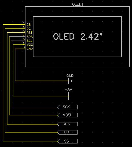
I think the best thing I can do is to post the code and the schematic part of the ATmega32U4 and the OLED. So here we go...
#include "U8glib.h"
/*
OLED    ARDUINO

GND      GND
VCC       5v
SCL       SCK (15 on Leonardo/Micro )
SDA       MOSI (16 on Leonardo/Micro)
RES        6
DC         7
CS         10 (SS)
*/
//OLED SSD1309 128x64 constructor
//U8GLIB_SSD1309_128X64 u8g( SCK, MOSI, SS, DC, RES );
U8GLIB_SSD1309_128X64 u8g( 15, 16, 10, 7, 6 );

void draw(void) {
  // graphic commands to redraw the complete screen should be placed here
  //u8g.setFont(u8g_font_unifont);
  u8g.setFont(u8g_font_5x8);
  //u8g.setFont(u8g_font_helvR10);
  u8g.drawStr( 0, 10, "RPM: 900");
  u8g.drawStr( 0, 22, "Oil: 87 C");
  u8g.drawStr( 0, 34, "Coolant: 94 C");
}

void setup(void) {
  // flip screen, if required
  // u8g.setRot180();

  // set SPI backup if required
  //u8g.setHardwareBackup(u8g_backup_avr_spi);

  // assign default color value
  if ( u8g.getMode() == U8G_MODE_R3G3B2 ) {
    u8g.setColorIndex(255);     // white
  }
  else if ( u8g.getMode() == U8G_MODE_GRAY2BIT ) {
    u8g.setColorIndex(3);         // max intensity
  }
  else if ( u8g.getMode() == U8G_MODE_BW ) {
    u8g.setColorIndex(1);         // pixel on
  }
  else if ( u8g.getMode() == U8G_MODE_HICOLOR ) {
    u8g.setHiColorByRGB(255,255,255);
  }

  pinMode(10, OUTPUT);
  pinMode(7, OUTPUT);
  pinMode(6, OUTPUT);
}

void loop(void) {
  // picture loop
  u8g.firstPage();
  do {
    draw();
  } while( u8g.nextPage() );

  // rebuild the picture after some delay
  delay(100);
}
The correspondent part of schematic are attached as picture.
And now the issue:
On the protoboard using another pins (I dont remember which ones) it worked. But I still use MOSI and SCK pins, for the other ones, RES, DC, and SS can be used normal digital pins (as I have learned before designign the pcb).
Now with the pin constructor as in the sketch, when I upload the sketch OR reset the ATmega, it shows image on the OLED for an half second... If I disconnect and reconnect the PCB to the USB is does the next thing:
-On connection the PC does the "usb device connected sound", and then noting on the OLED.
But when I reset with the RST button I have on the PCB it does this:
-On pressing button, "usb device disconected sound", when releasing, "usb device connected sound".
-After a few seconds, 7 or 8, again "usb device DISCONNECTED sound" on my laptop, and during this the OLED shows the text for a half second and turns it again off.
Really, it´s weird, I tried all kind of things, I checked the pin assignation on the constructor, and it must be correct.
Any idea?
Regards from Spain!!!