Have you got the FET wired up right? IRLZ44N is an N-type MOSFET, best used as a switch to ground rather than switch to power.
So you connect your circuit with power and where it goes to ground, the FET goes between circuit and ground.
The circuit connects to the FET Drain, it drains current from the circuit and you connect the FET Source to ground. In through Drain, out through Source, down to ground low-side switching.
I used 5V to switch 12V through 12V G4 led discs with IRLZ44N FETs, much less and they would not have lit.
GoForSmoke:
Have you got the FET wired up right? IRLZ44N is an N-type MOSFET, best used as a switch to ground rather than switch to power.
So you connect your circuit with power and where it goes to ground, the FET goes between circuit and ground.
The circuit connects to the FET Drain, it drains current from the circuit and you connect the FET Source to ground. In through Drain, out through Source, down to ground low-side switching.
I used 5V to switch 12V through 12V G4 led discs with IRLZ44N FETs, much less and they would not have lit.
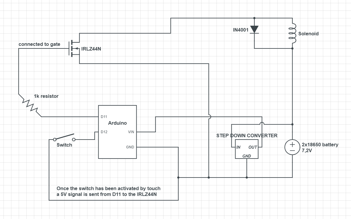
Right now I've made it so I'm sending a high(5V) voltage to gate in order activate it and the drain is connected to the solenoid, source connected to battery ground. Trying to switch Drain and source around allows 08.22V through but I can't use my switch to change the voltage.
Hi,
Can you post the code you are using for the post #23 test thanks.
Can you measure the voltage at the button input pin of the NANO when you press and release the button, and measure the voltage ar the gate of the MOSFET when you press and release the button?
caveat to the below: I have extra 328P-PU's and my Uno's have sockets. That plus know-how cuts the cost of mistakes deeply.
Oh, you might like this, I connected the IRLZ44N gate directly or through no more than 220 ohms to the IO pin.
I know that I connected 2N7777 directly before after web surfing 2N7777 circuits but I can't say 100% now (breadboard disassembled long ago) that IRLZ44N gate direct to pin is safe. I had spent time reading up on those too. Then I wired 220R or direct and it worked.
The FET should switch full ON by 2.0V. I don't see why 1KR between pin and gate should not work but try 220R?
TomGeorge:
Hi,
Can you post the code you are using for the post #23 test thanks.
Can you measure the voltage at the button input pin of the NANO when you press and release the button, and measure the voltage ar the gate of the MOSFET when you press and release the button?
Thanks.. Tom...
I'm still using the same code, haven't changed anything.
const int BTNpin = 12;
const int solPin = 11;
const int pixelPin = 10;

int BTNPinState = 0;
int solPinState = 0;
int pixelPinState = 0;

void setup() {
  // put your setup code here, to run once:
  pinMode(BTNpin, INPUT);
  pinMode(solPin, OUTPUT);
  pinMode(pixelPin, OUTPUT);
}

void loop() {
  // put your main code here, to run repeatedly:
  BTNpinState = digitalRead(BTNpin);

  if(BTNpinState == HIGH) {
    digitalWrite(solPin, HIGH);
    digitalWrite(pixelPin, HIGH);
  } else {
    digitalWrite(solPin, LOW);
    digitalWrite(pixelPin, LOW);
  }
}
I've only added pixelPin in the code as a preparation for the next step as soon as I get my mosfet to work.
You mean between D11 and the gate right, the switch just sends a signal to the Arduino nano? I can confirm the switch work since the L-led light on the Arduino nano reacts accordingly.
GoForSmoke:
caveat to the below: I have extra 328P-PU's and my Uno's have sockets. That plus know-how cuts the cost of mistakes deeply.
Oh, you might like this, I connected the IRLZ44N gate directly or through no more than 220 ohms to the IO pin.
I know that I connected 2N7777 directly before after web surfing 2N7777 circuits but I can't say 100% now (breadboard disassembled long ago) that IRLZ44N gate direct to pin is safe. I had spent time reading up on those too. Then I wired 220R or direct and it worked.
The FET should switch full ON by 2.0V. I don't see why 1KR between pin and gate should not work but try 220R?
I have some 220K and 220E resistors but not any 220R resistors. What is an IO ?
Artonn:
I have some 220K and 220E resistors but not any 220R resistors. What is an IO ?
220R is 220 Ohms Resistance abbreviation. you can add resistances by wiring them in serial. 2 100 ohm resistors in line is close enough to 220R for this to work.
IO is an Input-Output pin. The pins you setMode() as OUTPUT, INPUT or INPUT_PULLUP as opposed to 5V, GND, 3V3, reset, and the clock pins. 3V3 is 3.3V and in case you're wondering, I didn't make this up!
GoForSmoke:
220R is 220 Ohms Resistance abbreviation. you can add resistances by wiring them in serial. 2 100 ohm resistors in line is close enough to 220R for this to work.
IO is an Input-Output pin. The pins you setMode() as OUTPUT, INPUT or INPUT_PULLUP as opposed to 5V, GND, 3V3, reset, and the clock pins. 3V3 is 3.3V and in case you're wondering, I didn't make this up!
Thank you very much for your explanation, it makes sense! I'll see if I have any 100 ohm resistors. Do you know what the difference between the 220E 220R and 220K resistors are?
Artonn:
Thank you very much for your explanation, it makes sense! I'll see if I have any 100 ohm resistors. Do you know what the difference between the 220E 220R and 220K resistors are?
The K in 220K means 1000. The resistance should be 220000 Ohms plus or minus the tolerance %. Resistors commonly come in different precisions, 10%, 5%, 2% and 1% with color bands to show which. Look up the resistor color code if you ever need to look at a resistor and know what it should be. Use a meter to check the actual resistance if you need that.
220R is 220 Ohms, 220R-esistance.
The more you see these terms and think/read on them, the more the whole subject becomes clear. Study till you begin to lose focus then rest Repeat as necessary, your brain grows connections you need when you rest, the process of learning has a physical component: your wetware.
GoForSmoke:
The K in 220K means 1000. The resistance should be 220000 Ohms plus or minus the tolerance %. Resistors commonly come in different precisions, 10%, 5%, 2% and 1% with color bands to show which. Look up the resistor color code if you ever need to look at a resistor and know what it should be. Use a meter to check the actual resistance if you need that.
220R is 220 Ohms, 220R-esistance.
The more you see these terms and think/read on them, the more the whole subject becomes clear. Study till you begin to lose focus then rest Repeat as necessary, your brain grows connections you need when you rest, the process of learning has a physical component: your wetware.
Thank you very much for your explanation, it's appricated. Already starting to read up on them.
TomGeorge:
Use the force Luke..
Use your DMM.. to measure your resistors... :o :o :o
Tom...
Okay I found some very strange results.. So I took my multimeter and connected it to the ground of the arduino nano, while having the positive(red wire) on the digital pin 11. My multimeter says that there's 1.6V..
Artonn:
Okay I found some very strange results.. So I took my multimeter and connected it to the ground of the arduino nano, while having the positive(red wire) on the digital pin 11. My multimeter says that there's 1.6V..
Is that with the button pressed?
Can you measure the voltage at the button pin12 on the Nano with respect to gnd, with and without the button pressed.
Thanks.. Tom...
TomGeorge:
Is that with the button pressed?
Can you measure the voltage at the button pin12 on the Nano with respect to gnd, with and without the button pressed.
Thanks.. Tom...
Hi Tom, testing the BTN now. I've removed the switch, because for some reason it stopped working and I think it somehow killed my Arduino because it kind of acted strangely as well.. Luckily I have spare Arduino and I'm not using the switch untill I understand it better.
The new button sends in 4.8V to the Arduino. wow.. Now i get 4.8V out of D11 as well! Alright just put everything back together and it works!
But... I have to remove the diode I've put on for the solenoid, that's super weird. It doesn't work whenever i have a diode on it.
EDIT:
Oh shit, just tested it some more and the diode emitted a little smoke/vapor. It's hot.
The Cathode end of the diode, the end with the white band goes to the positive side of the solenoid, and the other end of the diode to the negative end of the solenoid.