I'm trying to use an Arduino nano to control a separate system that runs on a 9v battery, with an IRLZ44.
But for some reason I'm not able to get more than 4.5v through the IRLZ44, even when my battery can output 9v. I think it might have to do with the Arduino only sending 5v to the IRLZ44 to activate it? I'm no really sure, since I'm a beginner. Is there something i can do, to fix this problem?
const int BTNpin = 2;
const int solPin = 1;

int BTNpinState = 0;
int solPinState = 0;

void setup() {
  // put your setup code here, to run once:
  pinMode(BTNpin, INPUT);
  pinMode(solPin, OUTPUT);
}

void loop() {
  // put your main code here, to run repeatedly:
  BTNpinState = digitalRead(BTNpin);

  if(BTNpinState == HIGH) {
    digitalWrite(solPin, HIGH);
  } else {
    digitalWrite(solPin, LOW);
  }
}
Arduino power 5volt > V-in.
What does that mean.
Which Arduino (there are many).
Most need at least 6volt on V-in.
What is the current draw of the solenoid
I hope "9volt solenoid power" isn't a smoke alarm battery.
Most smoke alarm batteries can't supply more than ~50mA, and only for a very short time.
Leo..
Wawa:
Arduino power 5volt > V-in.
What does that mean.
Which Arduino (there are many).
Most need at least 6volt on V-in.
What is the current draw of the solenoid
I hope "9volt solenoid power" isn't a smoke alarm battery.
Most smoke alarm batteries can't supply more than ~50mA, and only for a very short time.
Leo..
I'm using an Arduino nano, just tried using two CGR18650 E batteries instead, didn't allow more than 4,5v through the IRLZ44 either. What is an V-in?
Artonn:
I'm using an Arduino nano, just tried using two CGR18650 E batteries instead,
didn't allow more than 4,5v through the IRLZ44 either.
What is an V-in?
7.2volt for the Nano, or for the solenoid.
V-in is the input of the onboard 5volt regulator.
V-in needs at least 6volt to make a stable 5volt for the MCU.
The Nano datasheet even states a minimum of 7volt.
With 5volt on V-in, you might only have 4volt on the MCU, and thus 4volt on the output pin.
4volt drive 'should' still be ok for the L version of the IRLZ44.
So, what is the current draw of that solenoid.
Leo..
Still don't know if you use the 18650 batteries for the solenoid, or for the Nano.
And, if used for the solenoid, how you power the Nano.
Maybe we have to see a real picture, since you seem to fail at answering all the questions.
Leo..
If you connect power to the external power plug it needs to be at least 7V for the regulator to work properly.
If you get a cheap buck converter, you can put 6V into it and get 5V out to apply to Arduino 5V pin. Your 9V battery converts to 5V at almost twice the current, converters exchange Volts and Amps with high efficiency within limits. The cheap ones max at 3A but it's smarter to use half that at most.
Adding batteries in parallel will add current available.
Wawa:
Still don't know if you use the 18650 batteries for the solenoid, or for the Nano.
And, if used for the solenoid, how you power the Nano.
Maybe we have to see a real picture, since you seem to fail at answering all the questions.
Leo..
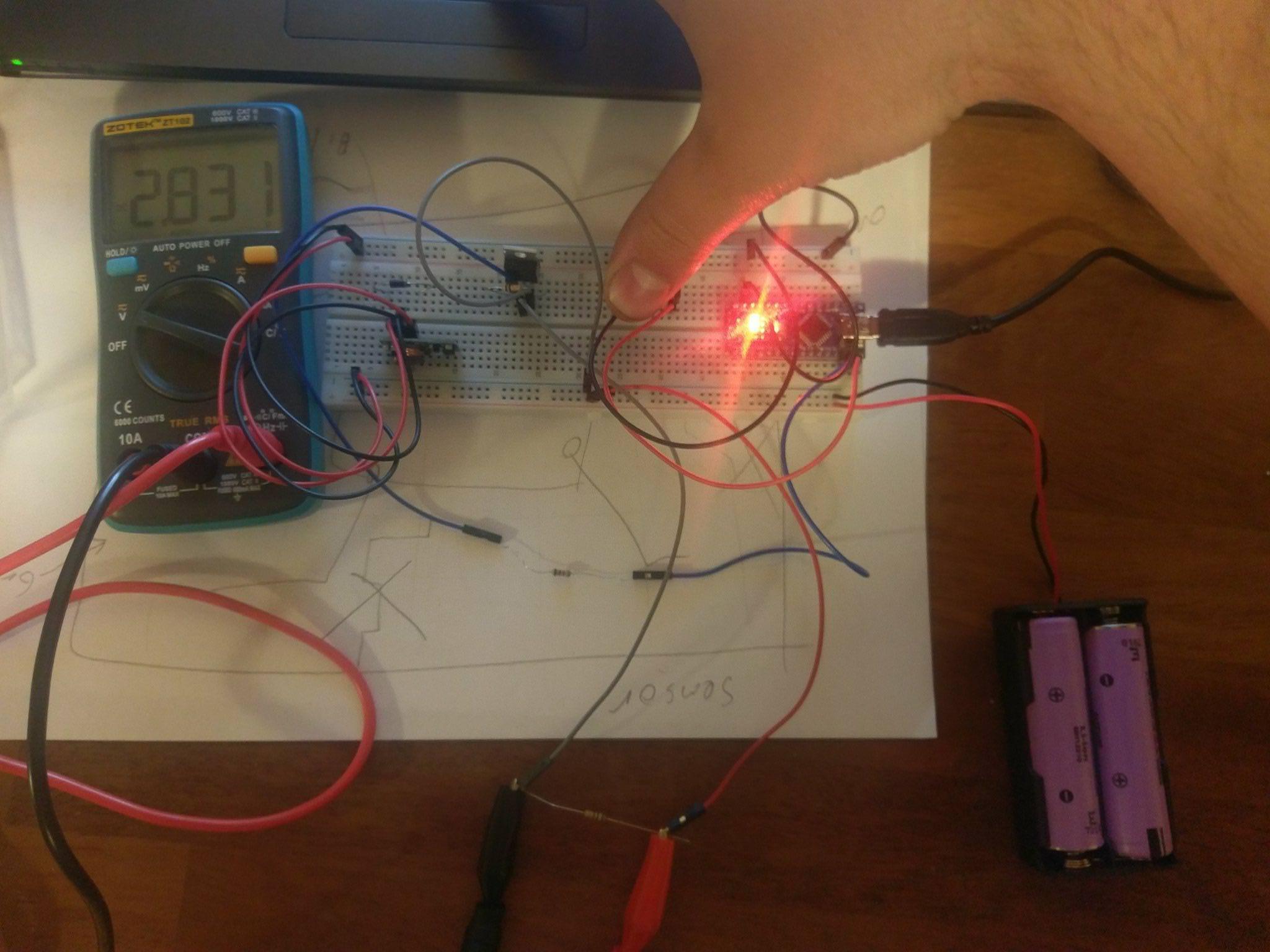
Hi,
Looking at this picture you supplied, you are measuring the voltage without a load on the MOSFET.
Put a 470R or 1K resistor between supply+ and the MOSFET drain to act as a load, and then measure the voltage.
Wawa:
Still don't know if you use the 18650 batteries for the solenoid, or for the Nano.
And, if used for the solenoid, how you power the Nano.
Maybe we have to see a real picture, since you seem to fail at answering all the questions.
Leo..
I'm sorry. The Arduino nano has it's own 5v power supply. While i''m using the 18650 batteries(2) for the solenoid, the battery on their own even the 9v battery can power the solenoid without problem themself.. But as soon as i connect them to my IRLZ44 and send a HIGH signal to the gate of the IRLZ44 from my Arduino nano pin 11(D2) on the schematic, only 4.5volts are coming through the IRLZ44.
The ground to the 5v supply for the Arduino nano is also connected to the ground of the two 18650 batteries i'm trying to get to power the solenoid through the IRLZ44.
It will show you how to ATTACH jpg and png files to your posts.
Removing you circuit diagram from your first post does not help this thread, in fact it makes the next 3 or 4 posts useless.
Can you please attach/post a copy of your circuit, in CAD or a picture of a hand drawn circuit in jpg, png?
Is your button/switch connecting 5V or gnd to the Arduino digital input.
Tom...
Hi tom. The button/switch BTNpin d12(D2 on schematic) is connected to ground. So what you're saying is any changes i make to the schematic and so on, should be posted as a comment instead of updating the original post?
TomGeorge:
Hi,
Looking at this picture you supplied, you are measuring the voltage without a load on the MOSFET.
Put a 470R or 1K resistor between supply+ and the MOSFET drain to act as a load, and then measure the voltage.


