Problems with Self Balancing Robot

Hi, I'm working on a self balancing robot but I'm having a bunch of different problems!

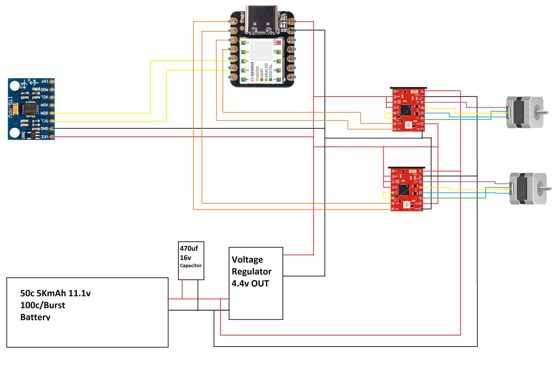
I'm using a Seeeduino XIAO.

The step motors(nema 17) are operating too weak and not smooth at all.

I can't get the PID library set up in a way that it returns good functional numbers to the OUTPUT variable in order to drive the motors.

This is my code:

#include<Wire.h>
#include <AccelStepper.h>
#include <PID_v1.h>


//MOTORS STUFF//////////////////////////////////////////////////////////////////////////////////////////////
// Define stepper motor connections and motor interface type. Motor interface type must be set to 1 when using a driver:
#define dirPinL 2
#define stepPinL 3
#define dirPinR 0
#define stepPinR 1
#define motorInterfaceType 1
// Creates a Motor instance
AccelStepper myStepperR(motorInterfaceType, stepPinR, dirPinR);
// Creates an instance
AccelStepper myStepperL(motorInterfaceType, stepPinL, dirPinL);
bool down, direcao;
int rSpeed, lSpeed;


//MPU SETUP//////////////////////////////////////////////////////////////////////////////////////////////
const int MPU_addr=0x68; int16_t AcX,AcY,AcZ,Tmp,GyX,GyY,GyZ;
int minVal=265; 
int maxVal=402;
double x; double y; double z;
long previousMillis = millis(); //Contador do tempo para ler MPU
long interval = 15;         //time for motor to swict direction


//PID SETUP/////////////////////////////////////////////////////////////////////////////////////////////////
 
double setpoint = 0;  // Define qual posicao o robo vai tentar manter
float Kp = 35;          // (P)roportional Tuning Parameter (20)
float Ki = 0;          // (I)ntegral Tuning Parameter     (70)   
float Kd = 0;          // (D)erivative Tuning Parameter       
float lastTime = 0;    // Records the time the function was last called
double output = 0;

PID PID1(&y/*imput value*/, &output, &setpoint, Kp, Ki, Kd, DIRECT);


void setup() {

  down = true; //comeca assumindo que o robo esta caido


//Preparando comunicacao I2C//////////////////////////////////////////////////////////////////////////////////////////////
    //MPU SETUP
  Wire.begin(); 
  Wire.setTimeout(2000);
  Wire.setClock(400000);
  Wire.beginTransmission(MPU_addr); 
  Wire.write(0x6B); 
  Wire.write(0); 
  Wire.endTransmission(true); 
  SerialUSB.begin(9600); 
  previousMillis = millis();


//Motors SETUP//////////////////////////////////////////////////////////////////////////////////////////////
  // set the maximum speed, acceleration factor,
  // initial speed and the target position

pinMode(dirPinL, OUTPUT);     // Left Motor Direction
pinMode(dirPinR, OUTPUT);     // Left Motor Direction

digitalWrite(dirPinL, LOW);
digitalWrite(dirPinR, HIGH);
  
  myStepperR.setMaxSpeed(10000);
  myStepperR.setAcceleration(100);
  myStepperR.setSpeed(10);
  myStepperR.moveTo(2000);
   
  myStepperL.setMaxSpeed(10000);
  myStepperL.setAcceleration(100);
  myStepperL.setSpeed(100);
  myStepperL.moveTo(2000);
  delay(3000);
  
//PID SETUP//////////////////////////////////////////////////////////////////////////////////////////
    PID1.SetMode(AUTOMATIC);              
    PID1.SetOutputLimits(-7000,7000);
    PID1.SetSampleTime(20);


}//end setup///


void loop() {


    previousMillis = millis();
    readMPU();
    
    if(y>-4&&y<4){
      y=0;
      output=0;
    }else{
      PID1.Compute();
      //output = myPID.step(setpoint, y);
    }

    
      Serial.print("y = ");
      Serial.print(y);
      Serial.print(" | output = ");
      Serial.print(output);
      Serial.print(" | direcao = ");
      Serial.println(direcao);


    if(down==false){

      
      while((millis()-previousMillis)<interval){


          myStepperR.setSpeed(output);
          myStepperL.setSpeed(output*(-1));
          myStepperR.runSpeed();
          myStepperL.runSpeed();
        
 
        }/*end while*/
    
      
    }else{
      
       Serial.println("DOWN");
      //Serial.println(y);
      
      //emd if down false
    }
      
  
}//endvoidloop


void readMPU(){


      Wire.beginTransmission(MPU_addr); 
      Wire.write(0x3B); 
      Wire.endTransmission(false); 
      Wire.requestFrom(MPU_addr,14,true); 
      AcX=Wire.read()<<8|Wire.read(); 
      AcY=Wire.read()<<8|Wire.read(); 
      AcZ=Wire.read()<<8|Wire.read(); 
      int xAng = map(AcX,minVal,maxVal,-90,90); 
      int yAng = map(AcY,minVal,maxVal,-90,90); 
      int zAng = map(AcZ,minVal,maxVal,-90,90);
  
      x= RAD_TO_DEG * (atan2(-yAng, -zAng)+PI); 
      y= RAD_TO_DEG * (atan2(-xAng, -zAng)+PI); 
      //y = yAng;
      z= RAD_TO_DEG * (atan2(-yAng, -xAng)+PI);

      Serial.print(" RAW y = ");
      Serial.print(y);
      Serial.print(" | ");

//delay(1000);


    //REMAP AND FORMAT Y
    if((y<45)&&(y>0)){
      y=map(y,45,0,300,0);//para tras
      y=y*(-1);
      down =false;
      direcao = false; //para tras
      digitalWrite(dirPinL, LOW);
      digitalWrite(dirPinR, HIGH);
    }else if((y<361)&&(y>321)){
              y=map(y,359,320,0,300);
              down =false;
              direcao = true; //pata frente
              digitalWrite(dirPinL, HIGH);
              digitalWrite(dirPinR, LOW);
           }else{
            down =true;
            y=0;
           }
      /**/
            
      //y=map(y,0,180,-90,90);


}


I'm pretty lost at this point and any help would be very welcomed!

Thank you!

The best way we can help you since we cannot stand beside you is for you to post technical links to all of the hardware items, sales listings usually do not have what we need. Posting a schematic, not a frizzy picture with all of the connections shown as you have wired them would be the biggest help. You have posted the code which is a big step in the correct direction. Be sure to show the power source and its rating.

Thank you so much!

I'm gonna make a schematic right now and reply soon.

I'm sorry for the poor quality of the drawing, let me know if there's anything else needed.

Controller: Seeeduino XIAO
Gyroscope: MPU6050
Stepper Drivers: A4988
Voltage Regulator: MP1584EN (Pretty Sure)
Stepper Motors: Nema 17

Thank you again!!

Adding a pic of the robot, maybe it helps identify something else.

Thank you!

Hello ianick. U are using the pid as only proportional? Pi and pd are ==0?
Simple samples did work for u? I mean put sample parameters and test with a set point for a non error output? Once u get that eorkin
I didnt see calculation for output variable.
Check this one

Hi @osval , thank you for your time!!

The values I have on the program for PID are at some stage of the tests that I’ve been performing. My only goal at this point is to make the robot stand up by itself. No need to move around yet.

My idea was to set the pid output between -7000 and 7000 and use that as a speed for the motors. I have a small “dead zone” on the gyro where it consider the robot stable and won’t produce any movement. The P value helps me make the output more or less responsive but the other two really messes it all up it seems like.

But I took the time to read the topic you attached to your answer and I’m about to work on it and see if I can use that information!

Thank you so much for the help!!

it is difficult to set the right parameters depending on the dynamic of your motors.
id suggest you play with pid and discover its response without and with motors. perhaps you can search for specific motor control with pid as I iimagine those stepper motors have a slow response and your mpu has a very fast response that you need to average to not be so erratic.
in this case your error is error= y_coordinate_from_mpu - steps_in_motor_representing_y_distance
then if you can translate how many steps in motor represent the span of y variable in distance your pid will have an error to become zero (which is the goal)
if you move let´s say 2 cm from y0 then your stepper motor must move 2cm to make error == 0 !
(speed will come with parameters of the pid isnt ???)

I’m gonna work on it today and let y’all know how it goes.

Thanks again!

"NEMA 17" tells us nothing useful about the motor. Please post the data sheet, or the specs on the rated current or rated voltage and coil resistance.

The A4988 driver must be adjusted to the proper current limit, and since it is limited to 1 Ampere per motor coil, may not be able to handle the maximum allowed for your motors.

Hi @jremington, thanks for the hint!

I adjusted the drivers as per directions that I got from this page: https://lastminuteengineers.com/a4988-stepper-motor-driver-arduino-tutorial/

I am using a 17HS4401-S.

This is a link for one of them, its not the same place where i got mine but it has all the information you may look for:

Click here to see it

Thank you for the help!

The motor is rated for 1.5 Amperes/phase, which is more than the 1 A/phase that the A4988 can handle continuously. To what value do you think(*) you set the current limit?

If set too high, the A4988 will overheat and shut down.

(*) The current limit formula given in the page you linked may not be correct for your version of the A4988, because it depends on the value of the current sense resistor that the manufacturer chooses to install on the PCB. Post a clear, focused photo of your driver and if the resistor is not obscured, we can tell you that value.

Hi, thanks again! I’m currently working on the software and testing some changes. No further results yet.

Here’s a picture that you requested me. I tested running the motors only and it seems like they perform well, however, I feel like they are weak. Maybe because it’s direct driven and the wheels are kind of big for it? Not sure.

Thank you again!!

Sorry, the resolution of that photo is too low to see the markings on the current sense resistors. They are most likely the two larger black components to the right of the A4988 chip.

I feel like they are weak

As I said, the driver could be overheating and shutting down. And you forgot to mention what you think the current setting is.

Hey, sorry, here’s a better picture:

I don’t remember the number but remember calculating what I needed and getting it right. But I’ll double check that and get that for you. I won’t be able to do it tonight but sometime this week for sure!!

What makes you think it was "right", if the motors are not working well? This is a critically important setting!

The current limiting resistors are marked R100, for 0.1 Ohm, so the correct formula for setting the current limit (see the A4988 data sheet) is

Vref = 8*(0.1 Ohm)*Imax

or Vref = 0.8 V for the maximum allowed current Imax of 1.0A.

Now I have a bigger problem!

I was trying a new code. Working on it I decided to calculate the distance to go in order to get the robot up right. I was looking at the numbers on the serial monitor when I decided to turn the motors on(I have a switch for it). Then I noticed that the numbers freeze after a few seconds. But they won't freeze if I don't turn the motors on.

Then I tried to load my original code(shared earlier in this thread) and it won't even read the values from the IMU. But when I upload the new code, it will read the values until i turn the motors on.

this is the new code:

// MPU6050 library
#include <MPU6050.h>   
 
// I2C communication library
#include <Wire.h>

// Motor Library 
#include <AccelStepper.h>

//  PID Library
#include <PID_v1.h>
 
// Create an MPU6050 object named mpu60500
MPU6050 mpu6050;     
 
//Define three-axis acceleration, three-axis gyroscope variables
int16_t ax, ay, az, gx, gy, gz; 
 
// The tilt angle
float Angle;
 
// Angular velocity along each axis as measured by the gyroscope
// The units are degrees per second.
float Gyro_x,Gyro_y,Gyro_z;  
 
///////////////////////Kalman_Filter////////////////////////////
// Covariance of gyroscope noise
float Q_angle = 0.001;  
 
// Covariance of gyroscope drift noise
float Q_gyro = 0.003;  
 
// Covariance of accelerometer
float R_angle = 0.5;    
char C_0 = 1;
 
// The filter sampling time.
float dt = 0.005;
 
// a function containing the Kalman gain is used to 
// calculate the deviation of the optimal estimate.
float K1 = 0.05; 
float K_0,K_1,t_0,t_1;
float angle_err;
 
// Gyroscope drift 
float q_bias;    
 
float accelz = 0;
float angle;
float angle_speed;
 
float Pdot[4] = { 0, 0, 0, 0};
float P[2][2] = {{ 1, 0 }, { 0, 1 }};
float  PCt_0, PCt_1, E;
//////////////////////Kalman_Filter/////////////////////////


//MOTORS STUFF////////////////////////////////////////////////////
// Define stepper motor connections and motor interface type. Motor interface type must be set to 1 when using a driver:
#define dirPinL 2
#define stepPinL 3
#define dirPinR 0
#define stepPinR 1
#define motorInterfaceType 1
// Creates a Motor instance
AccelStepper myStepperR(motorInterfaceType, stepPinR, dirPinR);
// Creates an instance
AccelStepper myStepperL(motorInterfaceType, stepPinL, dirPinL);
bool down, direcao;
int rSpeed, lSpeed;
////////////END MOTOR STUFF/////////////////////////////////////


//PID SETUP/////////////////////////////////////////////////////////////////////////////////////////////////
//Based on Y axis
//PID for distance to perform
double setpoint1 = 0;  // Define qual posicao o robo vai tentar manter
float Kp1 = 20;          // (P)roportional Tuning Parameter (20)
float Ki1 = 0;          // (I)ntegral Tuning Parameter     (70)   
float Kd1 = 0;          // (D)erivative Tuning Parameter       
float output1 = 0;

//PID PID1(&angle /*imput value*/ , &output1, &setpoint1, Kp1, Ki1, Kd1, DIRECT);


//Based on Y axis
//PID for speed of motors
double setpoint2 = 0;  // Define qual posicao o robo vai tentar manter
float Kp2 = 20;          // (P)roportional Tuning Parameter (20)
float Ki2 = 0;          // (I)ntegral Tuning Parameter     (70)   
float Kd2 = 0;          // (D)erivative Tuning Parameter       
float output2 = 0;

//PID PID2(&angle_speed/*imput value*/, &output2, &setpoint2, Kp2, Ki2, Kd2, DIRECT);


//PID SETUP/////////////////////////////////////////////////////////////////////////////////////////////////


// ROBOT SETTINGS AND CALCULATION VARIABLES ///////////////////////////////////////////////////////////////
float rHight = 9; // Hight from ground to IMU
float rWheelDiameter = 4.17;
int rStepsPerRev = 3200;
float distance_To_Go = 0;

// END ROBOT SETTINGS ///////////////////////////////////////////////////////////////

 
void setup() 
{
  // Join the I2C bus 
  Wire.begin();    
 
  // Set the baud rate
  Serial.begin(9600); 
 
  // 1.5 second delay
  delay(1500);
 
  // Initialize the MPU6050 sensor
  mpu6050.initialize();


//Motors SETUP//////////////////////////////////////////////////////////////////////////////////////////////
  // set the maximum speed, acceleration factor,
  // initial speed and the target position

pinMode(dirPinL, OUTPUT);     // Left Motor Direction
pinMode(dirPinR, OUTPUT);     // Left Motor Direction

digitalWrite(dirPinL, LOW);
digitalWrite(dirPinR, HIGH);
  
  myStepperR.setMaxSpeed(7000);
  myStepperR.setAcceleration(20000);
  myStepperR.setSpeed(10);
  myStepperR.moveTo(2000);
   
  myStepperL.setMaxSpeed(7000);
  myStepperL.setAcceleration(20000);
  myStepperL.setSpeed(100);
  myStepperL.moveTo(2000);
  delay(3000);


  // Delay 2 milliseconds
  delay(2);  
}
 
void loop() 
{
  Serial.print("Angle = ");
  Serial.print(Angle);
  Serial.print("  K_angle = ");
  Serial.print(angle);
  Serial.print("  Gyro_y = ");
  Serial.print(Gyro_y);
  Serial.print("  K_Gyro_y = ");
  Serial.print(angle_speed);
  Serial.print("  Distance to Go = ");
  Serial.println(distance_To_Go);
 
  // I2C to get MPU6050 six-axis ax ay az gx gy gz
  mpu6050.getMotion6(&ax, &ay, &az, &gx, &gy, &gz);     
 
  // Obtain angle and Kalman Filter 
  angle_calculate(ax, ay, az, gx, gy, gz, dt, Q_angle, Q_gyro, R_angle, C_0, K1); 
     
}
 
/////////////////////////////angle calculate///////////////////////
void angle_calculate(int16_t ax,int16_t ay,int16_t az,int16_t gx,int16_t gy,int16_t gz,float dt,float Q_angle,float Q_gyro,float R_angle,float C_0,float K1)
{
  // Radial rotation angle calculation formula; negative sign is direction processing
  Angle = -atan2(ax , az) * (180/ PI); //getting angle for y
 
  // The Y-axis angular velocity calculated by the gyroscope; the negative sign is the direction processing
  Gyro_y = -gy / 131;      
 
  // KalmanFilter 
  Kalman_Filter(Angle, Gyro_y);  
  Calculate_Distance(angle);          
}
////////////////////////////////////////////////////////////////
 
///////////////////////////////KalmanFilter/////////////////////
void Kalman_Filter(double angle_m, double gyro_m)
{
  // Prior estimate
  angle += (gyro_m - q_bias) * dt;          
  angle_err = angle_m - angle;
 
  // Differential of azimuth error covariance
  Pdot[0] = Q_angle - P[0][1] - P[1][0];    
  Pdot[1] = - P[1][1];
  Pdot[2] = - P[1][1];
  Pdot[3] = Q_gyro;
 
  // The integral of the covariance differential of the prior estimate error
  P[0][0] += Pdot[0] * dt;    
  P[0][1] += Pdot[1] * dt;
  P[1][0] += Pdot[2] * dt;
  P[1][1] += Pdot[3] * dt;
   
  // Intermediate variable of matrix multiplication
  PCt_0 = C_0 * P[0][0];
  PCt_1 = C_0 * P[1][0];
   
  // Denominator
  E = R_angle + C_0 * PCt_0;
   
  // Gain value
  K_0 = PCt_0 / E;
  K_1 = PCt_1 / E;
 
  // Intermediate variable of matrix multiplication
  t_0 = PCt_0;  
  t_1 = C_0 * P[0][1];
 
  // Posterior estimation error covariance
  P[0][0] -= K_0 * t_0;     
  P[0][1] -= K_0 * t_1;
  P[1][0] -= K_1 * t_0;
  P[1][1] -= K_1 * t_1;
 
  // Posterior estimation
  q_bias += K_1 * angle_err;    
 
  // The differential value of the output value; work out the optimal angular velocity
  angle_speed = gyro_m - q_bias;   
 
  ////Posterior estimation; work out the optimal angle
  angle += K_0 * angle_err; 
}


void Calculate_Distance(double angle_distance){

  if(angle_distance<0){
    angle_distance = angle_distance*(-1);
  }


  distance_To_Go = rHight * cos(90-angle_distance);
  
}

Inadequate power supply decoupling. Also, with those long, sloppy wires, you need a big, low ESR cap right across each motor driver power input terminals, as described here: Pololu - Understanding Destructive LC Voltage Spikes

That’s so weird because even with the motors off I can’t run my original program and get the imu measurements. And I was able to do it for hours in a row while working on it.

So should I move the capacitor that I have to close to the motor driver and add another one to the second driver?

Hi, I finally got an update on this!!!

Not working yet but I made progress!

Looked around, got bits of codes from different places.

I definitely believe I need to make sure my power source is reliable and plan on working on it this weekend!

A software problem I'm having is that I'm using a Kalman Filter algorithm(Not sure if its the right thing) and while it made it possible to balance the robot for few seconds, I noticed in the serial monitor that it drifts the balance point(0) and makes the robot fall. I can't figure out how to edit the function in order to fix it.

This is the code(still in development fase):

//#include <MsTimer2.h>        //internal timer 2
#include<Wire.h>
#include <AccelStepper.h>
#include <PID_v1.h>


//MOTORS STUFF//////////////////////////////////////////////////////////////////////////////////////////////
// Define stepper motor connections and motor interface type. Motor interface type must be set to 1 when using a driver:
#define dirPinL 2
#define stepPinL 3
#define dirPinR 0
#define stepPinR 1
#define motorInterfaceType 1
// Creates a Motor instance
AccelStepper myStepperR(motorInterfaceType, stepPinR, dirPinR);
// Creates an instance
AccelStepper myStepperL(motorInterfaceType, stepPinL, dirPinL);
bool down, direcao;
int rSpeed, lSpeed;


//MPU SETUP//////////////////////////////////////////////////////////////////////////////////////////////
const int MPU_addr=0x68; int16_t AcX,AcY,AcZ,Tmp,GyX,GyY,GyZ;
int minVal=265; 
int maxVal=402;
double x; double y; double z;
long previousMillis = millis(); //Contador do tempo para ler MPU
long interval = 35;         //time for motor to swict direction


///////////////////////Kalman_Filter////////////////////////////
float Q_angle = 0.01;  //Covariance of gyroscope noise 0.001
float Q_gyro = 0.001;    //Covariance of gyroscope drift noise 0.003
float R_angle = 0.6;    //Covariance of accelerometer 0.5
char C_0 = 1;
float dt = 0.004; //The value of dt is the filter sampling time
float K1 = 0.05; //  a function containing the Kalman gain; used to calculate the deviation of the optimal estimate 0.05
float K_0,K_1,t_0,t_1;
float angle_err;
float q_bias;    //gyroscope drift
 
float accelz = 0;
double angle;
float angleY_one;
float angle_speed;
 
float Pdot[4] = { 0, 0, 0, 0};
float P[2][2] = {{ 1, 0 }, { 0, 1 }};
float  PCt_0, PCt_1, E;
//////////////////////Kalman_Filter/////////////////////////


//PID SETUP/////////////////////////////////////////////////////////////////////////////////////////////////
 
double setpoint = 0;  // Define qual posicao o robo vai tentar manter
float Kp = 23;          // (P)roportional Tuning Parameter (20)
float Ki = 70;          // (I)ntegral Tuning Parameter     (70)   
float Kd = 0;          // (D)erivative Tuning Parameter       
float lastTime = 0;    // Records the time the function was last called
double output = 0;

PID PID1(&angle/*imput value after Kalman*/, &output, &setpoint, Kp, Ki, Kd, DIRECT);


void setup() {

  down = true; //comeca assumindo que o robo esta caido


//Preparando comunicacao I2C//////////////////////////////////////////////////////////////////////////////////////////////
    //MPU SETUP
  Wire.begin(); 
  Wire.setTimeout(2000);
  Wire.setClock(400000);
  Wire.beginTransmission(MPU_addr); 
  Wire.write(0x6B); 
  Wire.write(0); 
  Wire.endTransmission(true); 
  SerialUSB.begin(9600); 
  previousMillis = millis();


//Motors SETUP//////////////////////////////////////////////////////////////////////////////////////////////
  // set the maximum speed, acceleration factor,
  // initial speed and the target position

pinMode(dirPinL, OUTPUT);     // Left Motor Direction
pinMode(dirPinR, OUTPUT);     // Left Motor Direction

digitalWrite(dirPinL, LOW);
digitalWrite(dirPinR, HIGH);
  
  myStepperR.setMaxSpeed(7000);
  myStepperR.setAcceleration(500);
  myStepperR.setSpeed(10);
  myStepperR.moveTo(2000);
   
  myStepperL.setMaxSpeed(7000);
  myStepperL.setAcceleration(500);
  myStepperL.setSpeed(100);
  myStepperL.moveTo(2000);
  delay(3000);
  
//PID SETUP//////////////////////////////////////////////////////////////////////////////////////////
    PID1.SetMode(AUTOMATIC);              
    PID1.SetOutputLimits(-4000,4000);
    PID1.SetSampleTime(20);

}//end setup///


void loop() {


    previousMillis = millis();
    readMPU();
    
    if(y>-4&&y<4){
      y=0;
      output=0;
    }else{
      PID1.Compute();
      //output = myPID.step(setpoint, y);
    }

    
      Serial.print(" y = ");
      Serial.print(y);
      Serial.print(" | output = ");
      Serial.print(output);
      Serial.print(" | direcao = ");
      Serial.println(direcao);


    if(down==false){


      //move motors untill its time to check the robot's position again
      while((millis()-previousMillis)<interval){

          //Serial.println("TEST");
          myStepperR.setSpeed(output);
          myStepperL.setSpeed(output*(-1));
          myStepperR.run();
          myStepperL.run();
        
 
        }/*end while*/
    
      
    }else{

      myStepperR.stop();
      myStepperL.stop();
      
       Serial.println("DOWN");
      //Serial.println(y);
      
      //emd if down false
    }
      
  
}//endvoidloop


void readMPU(){

//AcX,AcY,AcZ,Tmp,GyX,GyY,GyZ;
      Wire.beginTransmission(MPU_addr); 
      Wire.write(0x3B); 
      Wire.endTransmission(false); 
      Wire.requestFrom(MPU_addr,14,true); 
      AcX=Wire.read()<<8|Wire.read(); 
      AcY=Wire.read()<<8|Wire.read(); 
      AcZ=Wire.read()<<8|Wire.read(); 
      Tmp=Wire.read()<<8|Wire.read(); 
      GyX=Wire.read()<<8|Wire.read(); 
      GyY=Wire.read()<<8|Wire.read(); 
      GyZ=Wire.read()<<8|Wire.read(); 
      int xAng = map(AcX,minVal,maxVal,-90,90); 
      int yAng = map(AcY,minVal,maxVal,-90,90); 
      int zAng = map(AcZ,minVal,maxVal,-90,90);
      
  
      x= RAD_TO_DEG * (atan2(-yAng, -zAng)+PI); 
      y= RAD_TO_DEG * (atan2(-xAng, -zAng)+PI); 
      //y = yAng;
      z= RAD_TO_DEG * (atan2(-yAng, -xAng)+PI);

      Serial.print(Tmp);
      Serial.print(" | RAW y = ");
      Serial.print(y);
      Serial.print(" | ");
      Serial.print(" RAW GyY = ");
      Serial.print(GyY);
      Serial.print(" | ");


    //REMAP AND FORMAT Y
    if((y<45)&&(y>0)){
      y=map(y,45,0,300,0);//para tras
      y=y*(-1);
      down =false;
      direcao = false; //para tras
      digitalWrite(dirPinL, LOW);
      digitalWrite(dirPinR, HIGH);
    }else if((y<361)&&(y>321)){
              y=map(y,359,320,0,300);
              down =false;
              direcao = true; //pata frente
              digitalWrite(dirPinL, HIGH);
              digitalWrite(dirPinR, LOW);
           }else{
            down =true;
            y=0;
           }
      /**/
            
      Kalman_Filter(y, GyY);
      Serial.print(" | Kalman y = ");
      Serial.print(angle);
      Serial.print(" | Kalman speed = ");
      Serial.print(angle_speed);
  
}

///////////////////////////////KalmanFilter/////////////////////
void Kalman_Filter(double angle_m, double gyro_m)
{
  angle += (gyro_m - q_bias) * dt;          //prior estimate
  angle_err = angle_m - angle;
   
  Pdot[0] = Q_angle - P[0][1] - P[1][0];    //The differential of the covariance of the prior estimate error 
  Pdot[1] = - P[1][1];
  Pdot[2] = - P[1][1];
  Pdot[3] = Q_gyro;
   
  P[0][0] += Pdot[0] * dt;    //The integral of the covariance differential of the prior estimate error
  P[0][1] += Pdot[1] * dt;
  P[1][0] += Pdot[2] * dt;
  P[1][1] += Pdot[3] * dt;
   
  //Intermediate variables in matrix multiplication
  PCt_0 = C_0 * P[0][0];
  PCt_1 = C_0 * P[1][0];
  //denominator
  E = R_angle + C_0 * PCt_0;
  //gain value
  K_0 = PCt_0 / E;
  K_1 = PCt_1 / E;
   
  t_0 = PCt_0;  //Intermediate variables in matrix multiplication 
  t_1 = C_0 * P[0][1];
   
  P[0][0] -= K_0 * t_0;    //the covariance of the prior estimate error 
  P[0][1] -= K_0 * t_1;
  P[1][0] -= K_1 * t_0;
  P[1][1] -= K_1 * t_1;
   
  q_bias += K_1 * angle_err;    //posterior estimate
  angle_speed = gyro_m - q_bias;   //The differential of the output value; get the optimal angular velocity
  angle += K_0 * angle_err; ////posterior estimate; get the optimal angular velocity
}


Thanks again!!!