Hi
I am working at an intrestiing project,i want using the processing to control a robot arm,i would drew a picture to show how the robot arm move ,like this
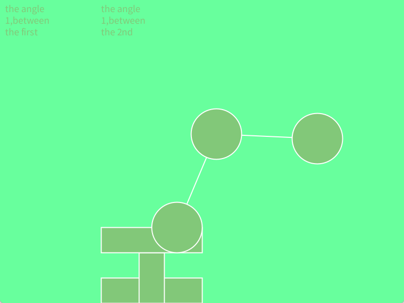
but there is a little difficulty,i want transmit the two data about the angle between the two circle and the original point at once,i don't know how to use the processing transmiting the data of array to arduino ,and how can i make the arduino recieve the signal.
and here is the processing code
import processing.serial.*;
Serial port;

float x1 = 350;
float y1 = 250;
float x2 = 150;
float y2 = 230;
float sz = 100;
color bgcolor;
float fixedLength = 200; // 设置固定线段长度
float angle_a4;
float line_first;
int[] x={};
float angle_1;
float angle_2;

void setup() {
  //port=new Serial(this,"COM5",9600); //Arduino板的端口号
  size(800, 600);
  colorMode(HSB);
  smooth();
  fill(80, 100, 200);
  bgcolor = color(100, 150, 255);
  background(bgcolor);
}

void draw() {
  background(bgcolor);
  Serial_print() ;
  // 检查鼠标是否在第一个圆上
  if(dist(x1, y1, mouseX, mouseY) < sz / 2) {
    cursor(HAND);
    if(mousePressed) {
      // 计算鼠标位置与固定点(350, 450)之间的角度
      float angle = atan2(mouseY - 450, mouseX - 350);
      //初始计算圆2与原始点的角
      float angle_a1=atan2(y2-450,x2-350);
      //计算圆圈2和圆圈1之间的角度
      float angle_a3=-(atan2(y1-y2,x1-x2));
      //get angle 4th ,in order to calculate the length of l1
      angle_a4=angle_a3+angle;
      // 根据固定长度和角度计算新的x1, y1坐标
      x1 = 350 + cos(angle) * fixedLength;
      y1 = 450 + sin(angle) * fixedLength;
      //calculate the l1
      line_first=sqrt(40000+40000-2*40000*cos(angle_a4));
      //refresh the circle 2nd's position
      x2 = 350 + cos(angle_a1) * line_first;
      y2 = 450 + sin(angle_a1) * line_first;
      strokeWeight(5);
    } else {
      strokeWeight(2);
    }
    stroke(255);
  }
  // 检查鼠标是否在第二个圆上
  else if(dist(x2, y2, mouseX, mouseY) < sz / 2) {
    cursor(HAND);
    if(mousePressed) {
      float angle = atan2(mouseY - y1, mouseX - x1);
      // 根据固定长度和角度计算新的x1, y1坐标
      if((dist(350, 450, mouseX, mouseY))<400){
      x2 = mouseX;
      y2 = mouseY;
      }
      //calculate the angle btetween 2nd circle and the original point
      float angle_a2=atan2(y2-450,x2-350);
      //calculate the distance between the 2nd circle and the original point
      float distance=dist(350,450,x2,y2);
      float angle_a1=acos(distance/400);
      if(atan2(y2-y1,x2-x1)>atan2(y1-450,x1-350)){
        angle_a1=-angle_a1;
      }
      float angle_a3=angle_a1+angle_a2;

      x1=350+200*cos(angle_a3);
      y1=450+200*sin(angle_a3);
      strokeWeight(5);
    } else {
      strokeWeight(2);
    }
    stroke(255);
  }
  else {
    cursor(ARROW);
  }
  String  txt_angle_1="the angle 1,between the first circle and the second : ";
  String  txt_angle_2="the angle 1,between the 2nd circle and the original : ";
  textSize(20);
  // 绘制线段和图形
  text(txt_angle_1, 10, 10, 100, 80);
  text(txt_angle_2, 200, 10, 100, 80);
  line(350, 450, x1, y1);
  line(x1, y1, x2, y2);
  rect(200, 550, 200, 50);
  rect(275, 500, 50, 100);
  rect(200, 450, 200, 50);
  ellipse(x1, y1, sz, sz);
  ellipse(x2, y2, sz, sz);
  ellipse(350, 450, sz, sz);
}
void Serial_print() {
  angle_1 = atan2(y1 - 450, x1 - 350);
  angle_2 = atan2(y2 - y1, x2 - x1)-angle_1;

  // 将角度转换为整数(假设您想要发送的角度是度数形式)
  int a_1 = -((int)(angle_1 * 57.3)); // 将弧度转换为度
  int b_1 = -((int)(angle_2 * 57.3))+90; // 将弧度转换为度

  // 构建包含a_1和b_1的数组
  int[] x = {a_1, b_1};

  // 发送数组到串行端口
  //for (int i = 0; i < x.length; i++) {
    // 将整数转换为两个字节并写入串行端口
    //port.write((byte)(x[i] & 0xFF)); // 发送低8位
    //port.write((byte)((x[i] >> 8) & 0xFF)); // 发送高8位
  //}
  print(a_1);
  print(";");
  println(b_1);
}
here is the arduino code
#include <Wire.h>
#include <Adafruit_PWMServoDriver.h>
#include <LiquidCrystal_I2C.h>

// 定义PCA9685的地址,默认为0x40
#define PCA9685_ADDRESS 0x40

// 定义伺服电机脉冲宽度范围
#define SERVOMIN  150 // This is the 'minimum' pulse length count (out of 4096)
#define SERVOMAX  600 // This is the 'maximum' pulse length count (out of 4096)

#define SERVO_FREQ 50 // Analog servos run at ~50 Hz updates

#define SERVO_CENTER ((SERVOMAX - SERVOMIN)/2 +SERVOMIN) // 中心位置脉冲宽度计数(对应90度)


// 定义伺服电机通道
#define SERVO_CHANNEL_1 0
#define SERVO_CHANNEL_2 1
#define SERVO_CHANNEL_3 2
#define SERVO_CHANNEL_4 3
#define SERVO_CHANNEL_5 4

LiquidCrystal_I2C lcd(0x27,16,2);  // set the LCD address to 0x3F for a 16 chars and 2 line display

int SERVO1;
int SERVO2;
int SERVO3;
int SERVO4;
int SERVO5;
int TURN=1;
int a=355;//260~480---88
int b=210;//170~470---120
int c=380;//195-475---112
int d=280;//280-470---76
int e=SERVOMIN;

int angle_1;
int angle_2;


// 初始化PCA9685对象
Adafruit_PWMServoDriver pwm = Adafruit_PWMServoDriver();

// Arduino pin numbers
const int SW_1 = 7; // digital pin connected to switch output
const int X_1 = A0; // analog pin connected to X output
const int Y_1 = A1; // analog pin connected to Y output
const int SW_2 = 6; // digital pin connected to switch output
const int X_2 = A2; // analog pin connected to X output
const int Y_2 = A3; // analog pin connected to Y output


int a_1=0;
int b_1=0;
int digitalSW1=0;
int a_2=0;
int b_2=0;
int digitalSW2=0;

void setup() {
  lcd.init();
  lcd.clear();
  lcd.backlight();      // Make sure backlight is on

  // Print a message on both lines of the LCD.

  // 初始化PCA9685
  pwm.begin();
  Serial.begin(9600);

  pinMode(SW_1, INPUT);
  digitalWrite(SW_1, HIGH);
  pinMode(SW_2, INPUT);
  digitalWrite(SW_2, HIGH);

  pwm.setOscillatorFrequency(27000000);
  pwm.setPWMFreq(SERVO_FREQ);  // Analog servos run at ~50 Hz updates

  // 将所有伺服电机设置到90度位置
  pwm.setPWM(SERVO_CHANNEL_1, 0, SERVO_CENTER);
  pwm.setPWM(SERVO_CHANNEL_2, 0, SERVO_CENTER);
  pwm.setPWM(SERVO_CHANNEL_3, 0, SERVO_CENTER);
  pwm.setPWM(SERVO_CHANNEL_4, 0, SERVO_CENTER);
  pwm.setPWM(SERVO_CHANNEL_5, 0, SERVO_CENTER);

  delay(10);

}


void loop() {
  a_1=analogRead(X_1);
  b_1=analogRead(Y_1);
  digitalSW1=digitalRead(SW_1);
  a_2=analogRead(X_2);
  b_2=analogRead(Y_2);
  digitalSW2=digitalRead(SW_2);

  rebuild();


  motor();

  delay(5);

}

void motor(){
  SERVO1=a;
  SERVO2=b;
  SERVO3=c;
  SERVO4=d;
  SERVO5=e;
    // 将所有伺服电机设置到90度位置
  pwm.setPWM(SERVO_CHANNEL_1, 0, SERVO1);
  pwm.setPWM(SERVO_CHANNEL_2, 0, SERVO2);
  pwm.setPWM(SERVO_CHANNEL_3, 0, SERVO3);
  pwm.setPWM(SERVO_CHANNEL_4, 0, SERVO4);
  pwm.setPWM(SERVO_CHANNEL_5, 0, SERVO5);
}

void rebuild(){
if (Serial.available() >= 4) {
    // 读取第一个整数的低8位和高8位
    int lowByteA1 = Serial.read();
    int highByteA1 = Serial.read();
    // 将两个字节合并为一个16位整数
    int a_1 = (highByteA1 << 8) | lowByteA1;

    // 读取第二个整数的低8位和高8位
    int lowByteB1 = Serial.read();
    int highByteB1 = Serial.read();
    // 将两个字节合并为一个16位整数
    int b_1 = (highByteB1 << 8) | lowByteB1;

    angle_1=a_1;
    angle_2=b_1;
}
  lcd.setCursor(2,0);   //Set cursor to character 2 on line 0
  lcd.print(angle_1);

  lcd.setCursor(2,1);   //Move cursor to character 2 on line 1
  lcd.print(angle_2);
}

