I am trying to us the AD5273 digital potentiometer to practice programming different resistance values. I found a tutorial on here that uses the AD5171 which from what I can see, is almost identical. I connected the circuit as it dictates in the tutorial and the LED is on solid when connected to the computer. When I upload the program, nothing happens and the LED stays the same brightness. The program is supposedly supposed to cycle through the 64 different positions of resistances and then repeat with the LED changing brightness each time. As I mentioned, this does not happen and the LED just stays the same brightness.
Ultimately the goal is to be able to enter in what value I want and hit program and have the LED adjust based on the resistance value I send to the chip but I was starting with this tutorial to try to help me learn the code but I have an issue somewhere. If anyone could shed any light on this topic it would be hugely helpful.
I am trying to use the AD5273 digital potentiometer to practice programming different resistance values. I found a tutorial on here that uses the AD5171 which from what I can see, is almost identical. I connected the circuit as it dictates in the tutorial and the LED is on solid when connected to the computer. When I upload the program, nothing happens and the LED stays the same brightness. The program is supposedly supposed to cycle through the 64 different positions of resistances and then repeat with the LED changing brightness each time. As I mentioned, this does not happen and the LED just stays the same brightness.
Ultimately the goal is to be able to enter in what value I want and hit program and have the LED adjust based on the resistance value I send to the chip but I was starting with this tutorial to try to help me learn the code but I have an issue somewhere. If anyone could shed any light on this topic it would be hugely helpful.
Sorry but a very poor tutorial designed to destroy your device. Assume the LED has a 2V forward drop then 220R will give an LED current of 13.6mA when the wiper is at full swing to 5V.
Now contrast this with the Absolute Maximum Rating for this device:-
Stresses above those listed under Absolute Maximum Ratings may cause permanent damage to the device. This is a stress rating only; functional operation of the device at these or any other conditions above those indicated in the operational section of this specification is not implied. Exposure to absolute maximum rating conditions for extended periods may affect device reliability.
Absolute Maximum Rating
IWB Continuous (RWB ≤ 1 kΩ, A open) ±5 mA
IWA Continuous (RWA ≤ 1 kΩ, B open) ±5 mA
So it is running the device at more than twice the maximum rating. Remove the LED and put a voltmeter in its place and slow down the resistance change and see if you can measure a voltage change.
Your digital pot might be toast or you might have wired it up wrong. Please provide a clear photograph of your wiring so we can check how you have wired it.
I had a quick look at the datasheet for the AD5273. I did not study it in detail to see if it is an appropriate substitute for the device mentioned in the tutorial.
However, the I2C address for writing appears to be 0x58 (decimal: 88) and the code you have included uses 0x2C (decimal: 44)
I can't cut and paste the code from your PDF attachment, but you should see where to change it.
If that does not work, find an I2C scanner and load it. This will report all the I2C addresses it finds.
If that does not help, alter the code to print out the integer return code it gets from the function call:
I will upload some pictures shortly. It was on recommendation that for absolute voltage/current purposes, the chips are interchangeable and my review of the datasheets gave me that similar impression.
As I may not have mentioned, I am a hobbyist trying to learn this stuff and appreciate the suggestions and insights as it helps me become better and learn. Unfortunately in my inexperience and quest to learn I have not reached the level of perfection & arrogance in the community that it seems raschemmel has been able to obtain.
I did run an I2C scanner and the device did not pop up either which I thought was strange.
I did change from 44 to 88 and it did nothing. I ran the scanner and it just kept scanning but nothing came up.
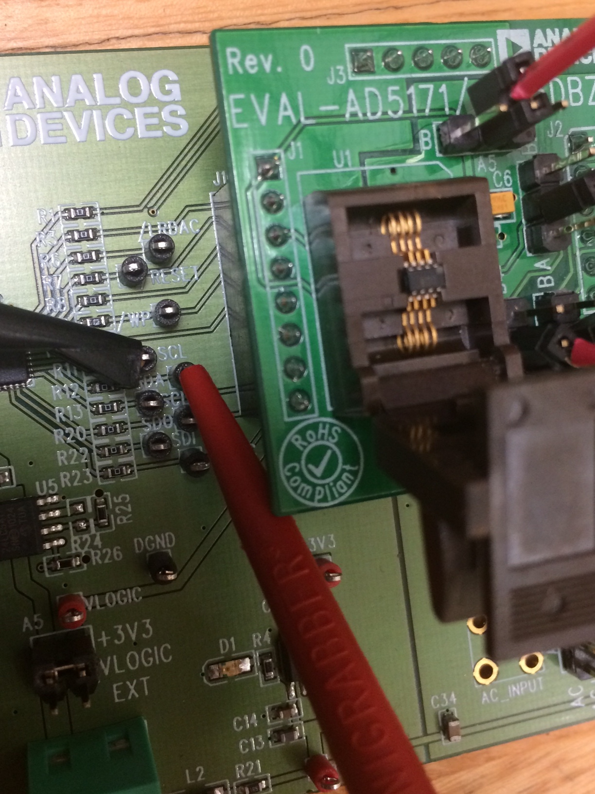
I am using the EVAL-AD5171/5273DBZ evaluation board to allow for ease of pin access. I did a continuity check on the pins to make sure I have the right pin out. Do you think this could be part of the issue?
Unfortunately in my inexperience and quest to learn I have not reached the level of perfection & arrogance in the community that it seems raschemmel has been able to obtain.
Please quote the part of my post that you felt was "arrogant" so I can better understand what I said wrong.
After finally looking at both datasheets and the tutorial (I didn't have time previously) I have to agree with Mike that the "issue" was the led current limiting resistor but I find it hard to believe that the pot actually fried due to an overcurrent of 15 mA.
Since you came here to learn and stated you are a newbie, if you intend to continue your hobby with electronics, your first order of business before building and running circuits should be learning Ohm's Law.
If you don't have a DMM (digital multimeter) then you should get one immediately.
I did run an I2C scanner and the device did not pop up either which I thought was strange.
You need to backtrack and verify your arduino I2C circuit is ok. Do you have ANY other I2C device that you can use to test the I2C circuit with the scanner ?
Have you heard of the I2C "GUESSER ?
Remove the dig pot and test the I2C interface with something else. Double check that you don't have SDA and SCL swapped.
Post your results.
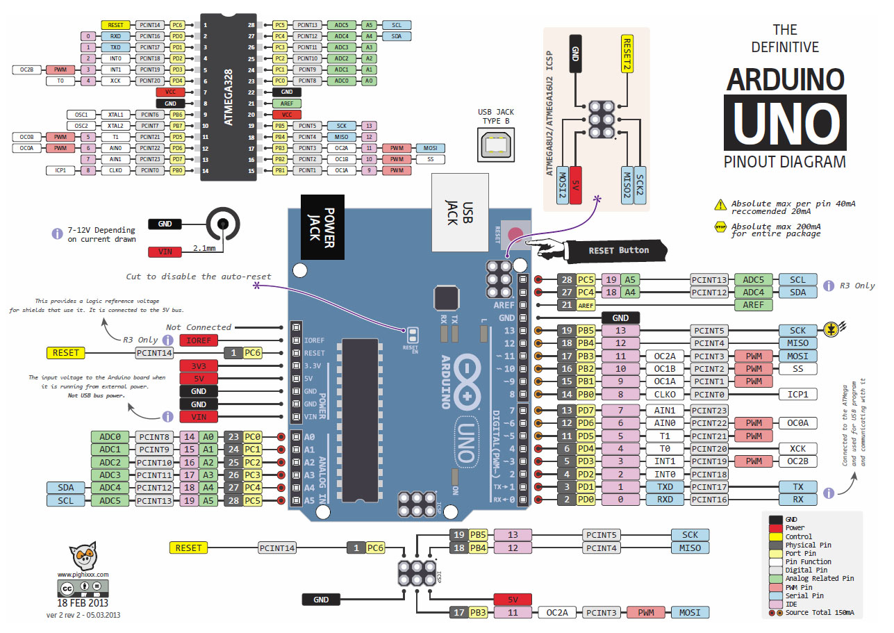
I set up a very basic circuit with the arduino UNO board where I was simply flashing an LED from Digital Pin Output 13. It worked fine. I have a second board and it worked for that as well.
Also probably an important piece of information that I forgot to mention, I am using the EVAL-AD5171/5273DBZ evaluation board from analog devices in order to access the pins for the digipot. Basically I did a continuity check to figure out the connector positions for each pin on the digipot and then ran them to a proto board to build the tutorial circuit. Could this be part of the problem?
Since my last post I replaced the 220 Ohm resistor with a 1k Ohm. I also replaced the digipot with a new one. There were no changes noted and the LED is just still solid light.
I attached some pictures of the circuit. It may be difficult to follow.. but essentially this is how its wired:
SDA connection point is wired to A5 on arduino Board
SCL connection point is wired to A4 on arduino board.
A (pin 8 ) & Vdd (pin 2) are wired to the 5 volts from the arduino board.
Ground (pin 3), B (pin7) and AD0 (pin 6) are wired to ground on the arduino board.
W (Pin 1) is wired to 1k resistor which is then in series with the LED which then connects to ground.
Side note: when I check the resistance across W right before the resistor as it is coming from the evaluation board) and A I get a resistance of about 4.00 Mohms. If this is acting like a normal potentiometer shouldn't I be getting some resistance value in the range of the total resistance of the chip? It seems way too high.
I'd like to thank you guys for your patience and ideas. Between your help and each time I let the magic smoke out of a component, I learn a little more.
It is hard to see the over all picture in those pictures. Image5, is that supposed to be the pull up resistors because if it is then that is not wired as per the diagram you posted.
It's probably important to add that I am a hobbyist doing this on a level with just enough information to make me dangerous so I may be overlooking or not understanding some things that are probably obvious to others.
In terms of converting it, I am not sure its relevant if I am just using the top part of the board to access the pins? I am not powering it through the USB but rather letting the power from the arduino board run through it as the mounting fixture on this evaluation board makes it easy to access the pins (its a surface mount and impossible to work with otherwise).
If the OP has connected the evaluation board up as in the PDF tutorial he attached in his first post, then the I2C scanner should have found it and it could not be much simpler.
aschartner1:
. . . I did a continuity check on the pins to make sure I have the right pin out. Do you think this could be part of the issue?
I'm guessing it is a wiring issue but what did you use here for the continuity check (unlucky if it was an insulation tester) ?
Do you have any other I2C devices you can check with the I2C scanner (eg a Real Time Clock module) ?
It's probably important to add that I am a hobbyist doing this on a level with just enough information to make me dangerous so I may be overlooking or not understanding some things that are probably obvious to others.
I did run an I2C scanner and the device did not pop up either which I thought was strange.
It's not strange when you consider you had the wrong address, the I2C lines were swapped and on top of that they were shorted. (FYI)
I updated the circuit to fix the short. I attached a picture of the update, one of a general overview of the setup and one of the evaluation board where the chip is held.
Still a solid light on & still cant find it with the scanner. I do not have any other I2C devices but I ordered some other digipot's that are I2C and they should be here today to try, particularly the AD 5171.
I tried another string of I2C scanner code in case their was something wrong with the first but it did the same thing. It just said "Scanning.." and nothing came up.
From the picture showing where the chip was held I used a fluke 189 meter and did a continuity check between each of the pins that come off of the chip and found where it correlates (beeps) to a connection on the evaluation board. You can visually see from the overview where they are connected.
From the spec sheet it indicated the dot on the chip identifies Pin 1. Moving down are pins 2,3 & 4. Then starting from the top of the chip on the opposite side of the dot is 8 and moving down are pins 7, 6, 5. At least that is my understanding from the spec sheet.
I linked the wrong evaluation document yesterday... The one I have been using I will attach in a minute. It is Analog Devices document UG-395.
The software is using address "44". The spec sheet for the AD 5273 says the slave address byte is 010110ADO0 which should come out to 44 right? Even if it was wrong the I2C scan should still pick up the chip and say what address it is though I thought?
Looking at the spec sheet, I'd say the I2C address for write commands to the AD5273 is 0b01011000 assuming no jumper is connected at position AD0.
That is 0x58 or decimal 88.
But, anyway its what the scanner sees thais important.
Incidentally, if you have another Arduino, you easily configure that as an I2C slave with a simple sketch to test the scanner etc.


