Programming structure for reverse forward work settings of electric motor (ac)

Is there anyone who can help me to revise the Arduino code that I made for setting up electric (AC) motors?

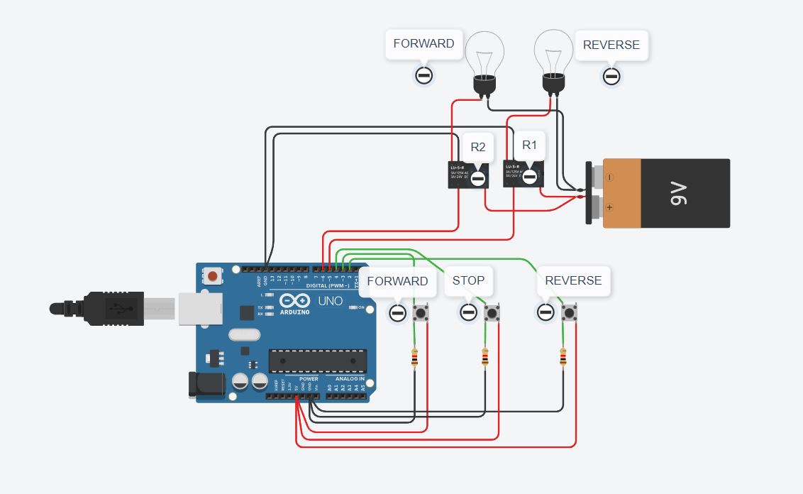
I use an Arduino Uno with 3 push buttons reverse, forward and stop then I use 2 relays for the reveres and forward contactors.

I want if I press the reverse push button then it cannot be interrupted by pressing the forward push button. This means that if the forward push button is pressed it will not function if the relay status is reverse on.

Likewise, if I press the forward push button, it cannot be interrupted by pressing the reverse push button. This means that if the reverse push button is pressed it will not function if the forward relay status is on.

Because I am a complete beginner in Arduino programming, I have tried various methods but have not succeeded.

Thank you if anyone is willing to help me.

Harkel

The code I have created is as follows:

const int reverseButtonPin = 2;
const int forwardButtonPin = 3;
const int stopAllButtonPin = 4;
const int relayPin1 = 5;
const int relayPin2 = 6;

void setup() {
pinMode(reverseButtonPin, INPUT_PULLUP);
pinMode(forwardButtonPin, INPUT_PULLUP);
pinMode(stopAllButtonPin, INPUT_PULLUP);

pinMode(relayPin1, OUTPUT);
pinMode(relayPin2, OUTPUT);
}

void loop() {
int reverseButtonState = digitalRead(reverseButtonPin);
int stopAllButtonState = digitalRead(stopAllButtonPin);
int forwardButtonState = digitalRead(forwardButtonPin);

// Mode Reverse
while (reverseButtonState == HIGH) {
digitalWrite(relayPin1, HIGH);
digitalWrite(relayPin2, LOW);
if (forwardButtonState == HIGH) {
digitalWrite(relayPin1, HIGH);
digitalWrite(relayPin2, LOW);
}
return;
}

// Mode Forward
while (forwardButtonState == HIGH) {
digitalWrite(relayPin1, LOW);
digitalWrite(relayPin2, HIGH);
if (reverseButtonState == HIGH) {
digitalWrite(relayPin1, LOW);
digitalWrite(relayPin2, HIGH);
}
return;
}

// Stop All
if (stopAllButtonState == HIGH) {
digitalWrite(relayPin1, LOW);
digitalWrite(relayPin2, LOW);
}
}

Welcome to the forum

Please follow the advice given in the link below when posting code, in particular the section entitled 'Posting code and common code problems'

Use code tags (the < CODE/ > icon above the compose window) to make it easier to read and copy for examination

https://forum.arduino.cc/t/how-to-get-the-best-out-of-this-forum

look this over

const int reverseButtonPin = 2;
const int forwardButtonPin = 3;
const int stopButtonPin    = 4;

const int relayForwardPin  = 5;
const int relayReversePin  = 6;

enum { ST_STOP, ST_FOR, ST_REV };
int state = ST_STOP;

void setup () {
    Serial.begin (9600);

    pinMode (reverseButtonPin, INPUT_PULLUP);
    pinMode (forwardButtonPin, INPUT_PULLUP);
    pinMode (stopButtonPin,    INPUT_PULLUP);

    pinMode (relayForwardPin, OUTPUT);
    pinMode (relayReversePin, OUTPUT);
}


void loop () {
    switch (state)  {
    case ST_STOP:
        if (LOW == digitalRead (forwardButtonPin)) {
            state = ST_FOR;
            Serial.println ("forward");
            digitalWrite (relayForwardPin, HIGH);
        }

        else if (LOW == digitalRead (reverseButtonPin)) {
            state = ST_REV;
            Serial.println ("reverse");
            digitalWrite (relayReversePin, HIGH);
        }
        break;

    case ST_FOR:
    case ST_REV:
        if (LOW == digitalRead (stopButtonPin)) {
            state = ST_STOP;
            Serial.println ("stop");
            digitalWrite (relayForwardPin, LOW);
            digitalWrite (relayReversePin, LOW);
        }
        break;
    }
}

Thank you for helping me.

However, when I copy and paste the code you created into Tinkercad, the results are still not correct.

The result is:
When the simulation is run before I press any push button, the reverse relay starts first (all of them should have turned off first in the initial condition).

Second, when I press the forward push button, the forward relay is on but only for a moment and then the reverse relay continues on.

Third, the stop all push button doesn't work when pressed.

buttons are typically connected between the pin and ground, the pin configured as INPUT_PULLUP to use the internal pullup resistor which pulls the pin HIGH and when pressed, the button pulls the pin LOW.

looks like you enabled the internal pullup resistor as well as adding external pull-down resistors.

since i just saw the INPUT_PULLUP i assumed the logic should be to recognize a button press when the pin is pulled LOW.

if you want to keep the external pull-down resistors, change the pin configuration to INPUT and change the logic to test for HIGH ==

I have tried again by replacing INPUT_PULLUP with INPUT but the results have not changed.

Excuse me. I tried again and replaced LOW with HIGH and it turned out the results were correct.

Thank you very much for your help. May you always be successful.

This topic was automatically closed 180 days after the last reply. New replies are no longer allowed.