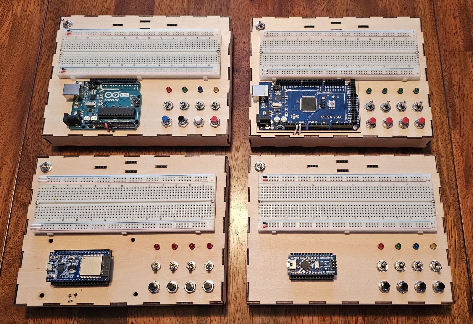
I never like struggling when working on things, so I tend to put in some effort to eliminate frustrations. I put my laser to work making boxes and after a few hours of tedious soldering, I now have an organized and enjoyable way to prototyping. The (+) and (-) rows on the breadboards are connected to the microcontrollers eliminating that connection, and I added a toggle switch in the top-left corner of the box to turn that connection off when needed. The toggle switches are the On-Off-On type.
Very good. And I am envious, but unfortunately at the opposite end of the spectrum. Always hunting around for things and making do with what I find when I KNOW that the part I need is squirreled away somewhere.
The psychology of this is concerning. You KNOW that the organization is beneficial. I, unfortunately still view those organizational tasks as "non-productive" time. Or maybe it is just laziness? Old habits are hard to break.
I think I would have created a PCB to mount the LEDs etc, to reduce the amount of wiring.
I have been working on something slightly different, which combines a breadboard approach with a modular system like Grove or Tinkerkit. I am not sure it is better than a simple breadboard though.
Have you considered adding a separate power supply and only connect the GND to the breadboard so that you don't use the Arduino as a power supply
➜ USB to the Arduino
➜ extra power source for the breadboard
➜ some power sockets for extra equipment where you don't wish to go through the breadboard
if you play with motors, led strips, GPRS shields or other stuff requiring too much current then you'd be ready
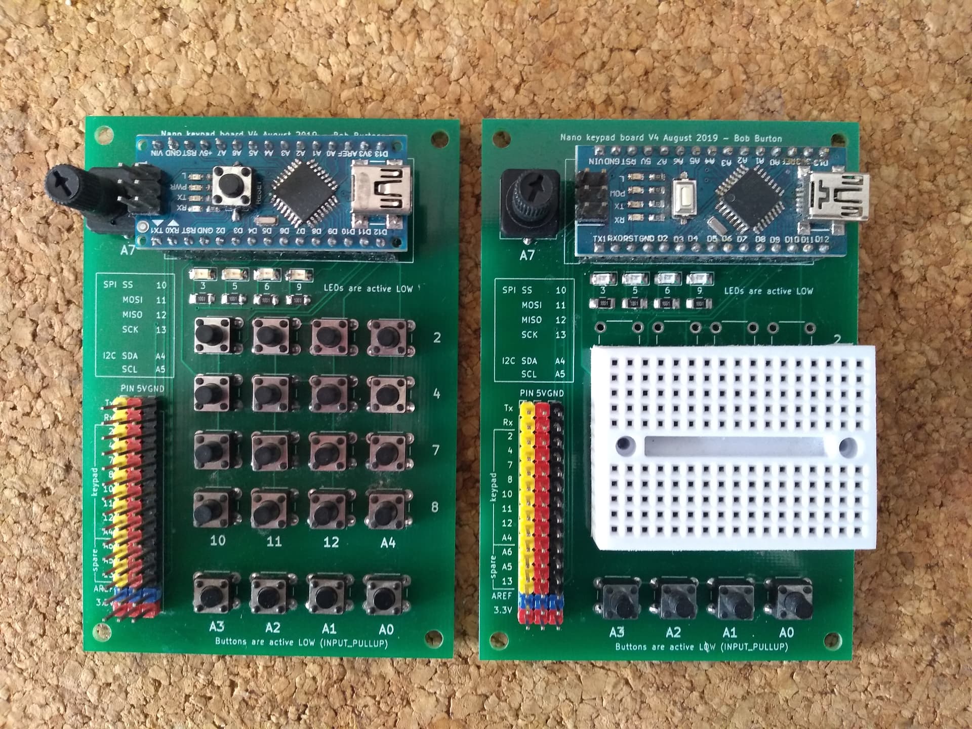
In the same vein I designed a PCB to hold a Nano, 4 LEDs on PWM pins, 4 buttons, a 4x4 keypad and a pot on an analogue input. When the 4x4 keypad is used there are 3 pins spare for general use (A6, A5 and 13) along with pins 0 and 1 if used appropriately.
When a smaller keypad is used the unused row and column pins become available for GPIO use
The second board shown below is the same as the first but with a mini breadboard substituted for the keypad buttons
These two boards cover the vast majority of my needs for tinkering with Nano compatible projects and the PCB will, of course, accept any Nano compatible Arduino board such as the Nano 33 IOT if WiFi or Bluetooth connectivity is required
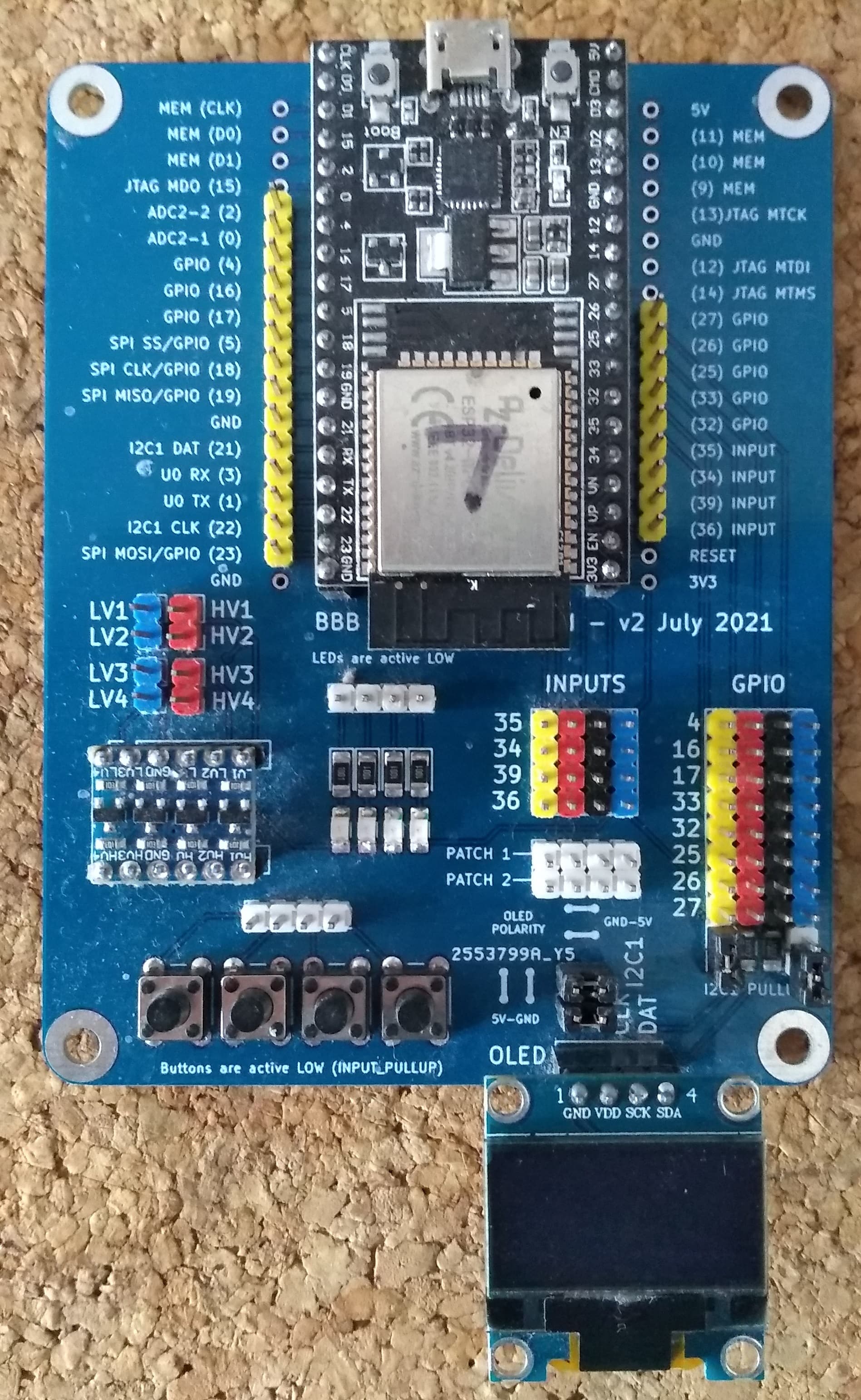
In the same vein, the second picture shows an ESP32 board with 4 LEDs, 4 pushbuttons, voltage level shifter and spare pins broken out to pin headers. The OLED screen at the bottom right plugs into an I2C socket which can be configured in one of 2 power pin arrangements common on such screens (5V and GND reversed !) and the board has I2C data line pullup resistors selectable using jumpers should they be required
As with the Nano board this meets most of my needs when tinkering with the ESP32, especially with WiFi and Bluetooth based projects
Both boards make testing a lot of sketches very easy as problems presented here are often caused by failures of logic rather than hardware. The LEDs can be used as stand ins for digital or analogue outputs, the buttons for digital inputs and the potentiometer for analogue input
The ability to just upload a sketch and have buttons, LEDs and a pot available without the need to build the circuit is a great boon. I have ideas to extend the boards but want to keep them within the cheap board sizes available from PCBWay and JLCPCB if possible
Apart from anything else it gave me a couple of projects to practice designing PCBs and soldering a few surface mount components on something that I could afford to mess up
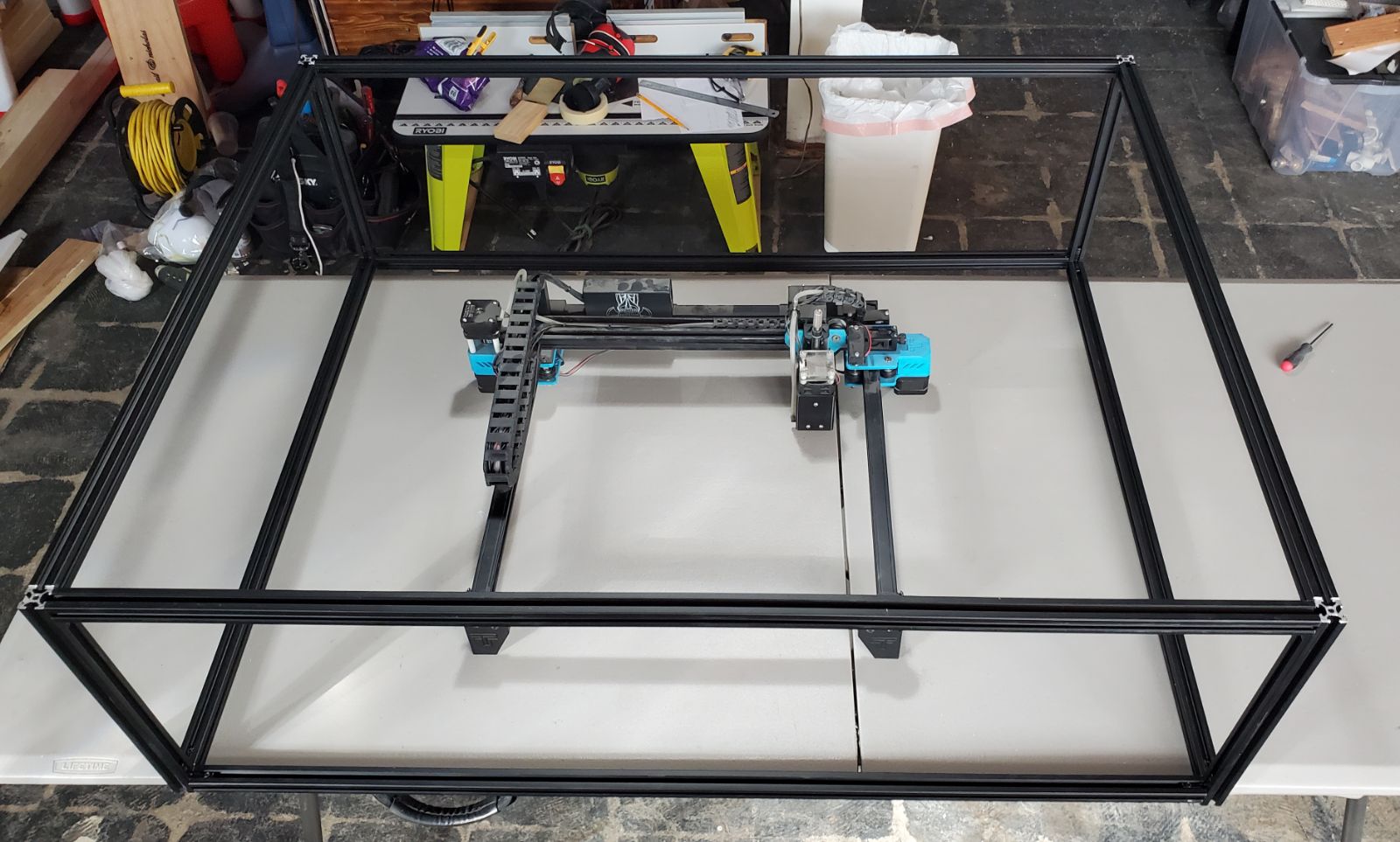
I've had a lot of fun with my laser. I'm saving for a more powerful head unit as mine is a weak 5.5 watt. I started small with the Two Trees TTS-55 to see if it was something I wanted to pursue. The stock unit max'd out at 11x11.5 inches and I wanted to be able to engrave larger objects, such as full size kitchen cutting boards and whiskey barrel lids. So, I purchased a box of 100cm long V-slot , and enlarged it. It's worked out really well.
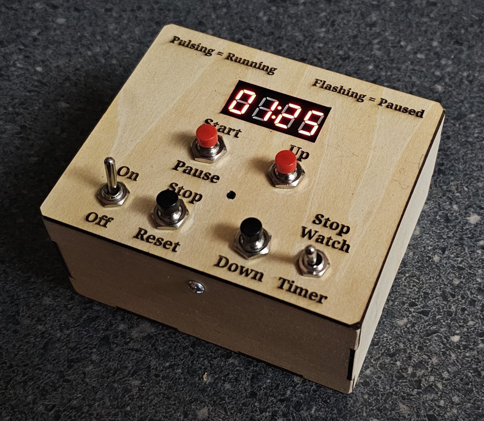
I made a timer/stopwatch for use with various games that we invent for the grandkids. The 2mm plywood enclosure looks pretty cool. It's awesome how Lightburn utilizes "layers". One layer engraved all of the labels, then the next layer cut all of the holes and six sides of the box.
Not quite my first attempt. I had previously used a practice SMD soldering board and a previous version of this the board that turned out to have a design problem that I had introduced just before sending it off to be made and had not tested beforehand. I had changed some pins used by the keypad to make the PCB trace routing neater and used pin 13 for one of the keypad pins.
When I got the PCB I built it the keypad did not work properly. Using pin 13 for the keypad turned out not to be a good idea due to its use by the built in LED
To be honest, I have no idea. I can't remember why I did it that way. It would probably be one of the things that I would change if I ever updated the board. That and maybe an option to use active LOW or HIGH with the buttons, perhaps by using jumpers or a DIP switch
I have a handful of these that I use when needed. So far, my projects have only incorporate components such as Micro SD, RTC, and BT modules, so power hasn't been an issue.