Project: Electromagnetic locks with Arduino

Hi guys!
I have a huge problem with my circuit. I did not see any mistakes, could you please help me find any?
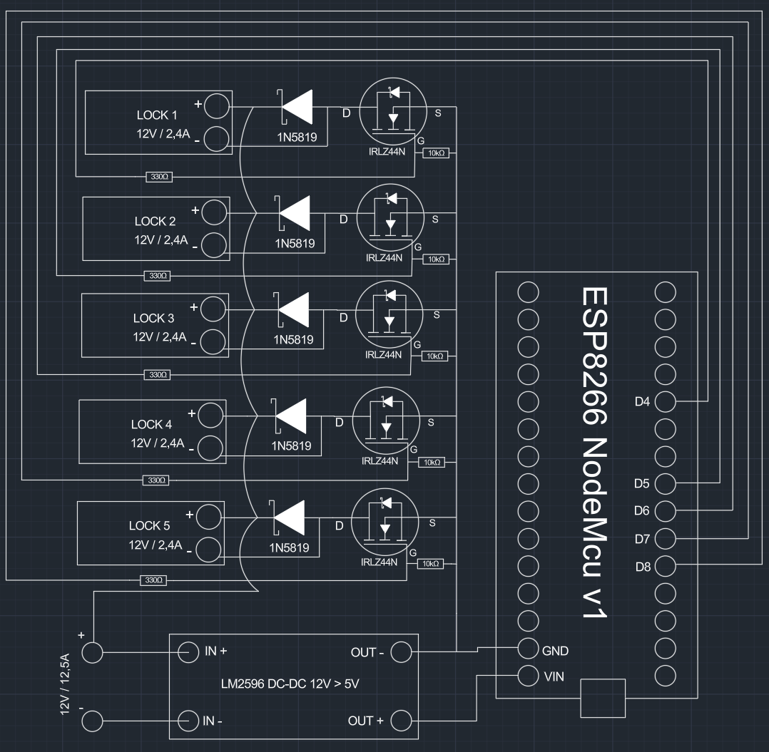
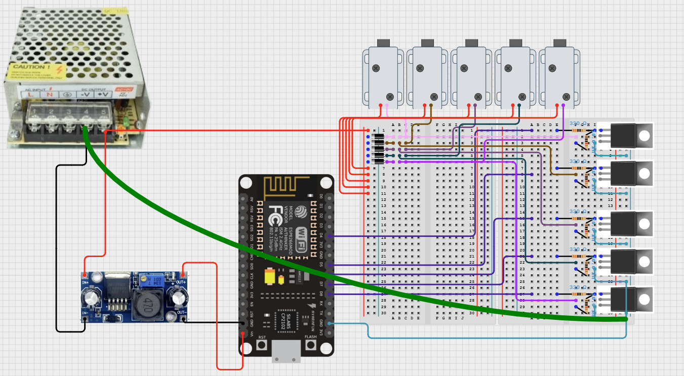
I created this circuit:


To make a shelf with locks controlled by ESP 8266 NodeMCU v1 and mobile app.
I used MOSFET IRLZ44N, IN5819 diodes, LM2596 Buck 12V -> 5V, PSU 12V/12.5A and 330ohm, 10kOhm resistors. I know it's a liitle messy but I did my best.
Here is a litlle code I made for control only one lock for now:

#include <ESP8266WiFi.h>
#include <ESP8266WebServer.h>

const char* ssid = "";
const char* password = "";

IPAddress local_IP(192, 168, 1, 192);
IPAddress gateway(192, 168, 1, 1);
IPAddress subnet(255, 255, 255, 0);
IPAddress dns(192, 168, 1, 1);

const int lockPin = D6;  // GPIO12

ESP8266WebServer server(80);

void handleUnlock() {
  Serial.println("Otwarto!");
  digitalWrite(lockPin, HIGH);   // otwarcie zamka
  delay(300);                    // 200 ms
  digitalWrite(lockPin, LOW);    // zamyka
  server.send(200, "text/plain", "Unlocked");
  
}

void setup() {
  pinMode(lockPin, OUTPUT);
  digitalWrite(lockPin, LOW);

  Serial.begin(115200);
  delay(100);

  // Ustawianie statycznego IP
  if (!WiFi.config(local_IP, gateway, subnet, dns)) {
    Serial.println("Błąd ustawiania statycznego IP");
  }

  WiFi.begin(ssid, password);

  Serial.print("Łączenie z WiFi");
  while (WiFi.status() != WL_CONNECTED) {
    delay(500);
    Serial.print(".");
  }

  Serial.println();
  Serial.print("Połączono! IP: ");
  Serial.println(WiFi.localIP());

  server.on("/unlock", handleUnlock);
  server.begin();
  Serial.println("Serwer HTTP działa.");
}

void loop() {
  server.handleClient();
}

When I firstly attached one MOSFET with one lock everything worked and lock opened. When I added 4 more the ESP Overheated and stopped working, I can't even upload any sketch for that.
I have no idea what did go wrong, do you have any ideas?

PS. I'm sorry if I forgot about something, it's my second post.
Thank!

Please give a symbolic circuit diagram, no Fritzing. Details of only one of multiple similar inputs/outputs are sufficient. Hand drawing is sufficient.

I cannot find any resistors?

The first load may have killed the ESP by EMF.

1 Like

I moved your topic to a more appropriate forum category @jszulc.

The Nano Family > Nano ESP32 category you chose is only used for discussions directly related to the Arduino Nano ESP32 board.

In the future, when creating a topic please take the time to pick the forum category that best suits the subject of your question. There is an "About the _____ category" topic at the top of each category that explains its purpose.

Thanks in advance for your cooperation.

1 Like

Hi, thank you so much. I made a circuit diagram for you. I'm beginner at drawing but I hope now everything will be clear.

Arch lines are not connected with straight (All cathodes from diodes are connected with one line to 12V from PSU)

Also I have to tell that ESP burned while only one lock was connected to power. Diodes was in.

You should have had a ground connection directly to the MOSFET sources (Green wire) Without it you have very high currents going directly through the ESP board

Thanks for sharing all the details it really helps! From what you described, it sounds like the ESP may have been exposed to voltage spikes, possibly due to inductive kickback from the locks. Even with diodes, fast switching or wiring issues can still cause damage. A flyback diode placement check and isolating the ESP with optocouplers or a driver circuit might help. Keep going you’re close.

Thank you, do you think it will be enough? Or maybe there are more mistakes which can assue problems?
I don't want to burn another ESP board :frowning:

Unfortunately it happened when only one lock was connected to power. Before I connected all MOSFETs I've done only one for one lock and there were no problems at all. I will try to use optocouplers and a driver circuit. Could you please give me more informations how to do that? I don't want to risk another ESP :frowning:

Using a solderless breadboard is not the best solution when dealing with high currents. I seen one online source for those locks that said they require 1.1A, so for 4 it's 4.4A
I see you diagram says 2.4A for the lock, is that correct?

The IRLZ44N is not the best choice since it may not fully turn on with a gate voltage of only 3.3V.

Connecting the negative input-output of the buck converter is mandatory if the +input is used for the locks. But is that connection also allowed in the data sheet?

The rest looks good to me.

I bought these ones from alibaba - Locks - I also got catalogue for this product and it says locks need 2,4A.

My PSU is 12,5A but I don't want to open all of them at once. It will be sequences with 300ms delay.

Do you have any other ideas how to do that? I don't must to use IRLZ44N, other techniques are also good for me.

Waste of time that is not your problem.

You fried your chip by not having a diode across the lock coil. The inductive kick back would have killed it, or at the best damaged it. When this happens the lifetime of the components involved are shortened. So it may have appeared to work for a bit.

Do you think connecting ground from PSU directly to mosfets source will be enough? I won't get ESP burns anymore?

I used diodes for the locks (1N5819). Look on the diagram please. It's not enough to make it safe?

That's fine, I think that you understand the problem :slight_smile:

Next candidate it the buck converter. Can you give a link to the data sheet? Negative input and output should already be connected inside the converter and hopefully is not burnt on the board.

Do you mean only one will be open at any time and never two or more?

That's correct. I don't need to do that. Maybe one time I will try to open 2 at once, but I think I have enough current for that.

You used them incorrectly the diagram shows they were not across the coil, but in series with it.
In the following diagram treat your coil as if it were the motor.

And just treat the relay contacts as the FETs that drive your circuit.

That should be good - LM2596

Yes, ground from input and output are connected. That's why I didn't connect PSU ground straightly to MOSFETs source.

Well that's not the problem. Two on at once would require 4.8A and that's not good for a solderless breadboard. Also 2.4A may be too high for the IRLZ44N with only 3.3V gate drive.