raschemmel:
The answer to your question is in that paragraph.
There are only two possibilities.
- zener is forward biased
- zener is reversed biased.
You said you read it. Do the math..
That does not looks like a schematic to me. I asked for a schematic example.
I know that a Zener diode can be used in booth directions. But since i can't use only the Zener diode, i asked for an example schematic where the Zener diode is involved. If it's possible of course.
You keep ignoring the replies and asking for a schematic . How's that working out for you ?
What happens the zener isin parallel instead of in series ?
Has it occurred to you that you aren't going to get
the answer handed to you on a silver platter ?
That maybe you might have to think for yourself ?
raschemmel:
You keep ignoring the replies and asking for a schematic . How's that working out for you ?
I do not ignore the replies. I just told you, i've read it.
How thats working out for me? All works fine.
I think i stop here.
Good for you.
That wasn't so hard was it ?
Google is your friend.
Now can you explain why it works ?
Good for you.
Thanks.
That wasn't so hard was it ?
No, it's never hard to find things on google.
Google is your friend.
Oh, yes 
Now can you explain why it works ?
I haven't tried it yet, and i think you already know why and or how it works.
You keep telling us you came here to learn so stop what you're doing and take a second to think
about it. If it's a 2.8Vzener in series with a 20 mA current limiting resistor (2.8V/.020amA=149 ohms)
and the battery voltage drops to 3V, if 10mA flows through the 140 ohm resistor, how much voltage
is dropped across the resistor ?
If the base voltage is 0.7V when the transistor is on, what voltage zener do you need so the
voltage from GND = 3V -0.7V-Vz ?
What happens when the Vcc = Vz ?
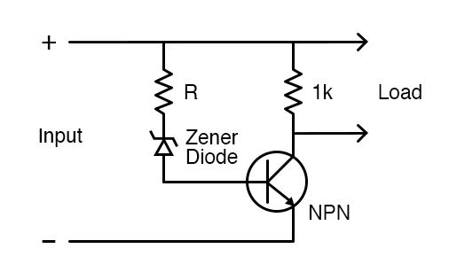
Note : what makes this circuit work is the transistor
conducts the load and the zener simply controls
the transistor, but how ?
Don’t worry. I think i’m going to find it out
When Vcc=(VR+Vz), the the zener 'shuts off' and the zener current limiting resistor (R) voltage drop (VR) goes to 0V
VBase(ON)= 0.7V,
so if VBatt= 4V, then (VBatt-0.7V)=(4V-0.7V)=3.3V
If Vz=2.8V,
.'. VBatt-VR-Vz=VBatt-0.7V=(4V-0.7V)=3.3V
Vz=2.8V, then VBatt-VR-Vz
=(4V-VR-2.8V-VBase)=>VR=(4V-2.8V-0.7V)=0.5V
VR=0.5V
R=VR/Iz
Which brings us to the question:"WHAT is Iz ?
Iz IS CHOSEN BY THE DESIGNER ! (THAT'S YOU !)
HOW DO YOU DO THAT ?
STEP-1: READ the DATASHEET !
"https://www.mouser.com/datasheet/2/427/1n5221-1767759.pdf"
Test current IZT1.7 to 20mA
STEP-2: (PICK A VALUE BETWEEN 1.7 and 20mA)
Let Iz=15mA (0.0150A)
STEP-3: Calulate R, based on Iz
IF VR=0.5V, AND IR=Iz , THEN R= VR/IR=0.5V/0.0150A = 33 ohms
R= 33.3 ohms
STEP-4: Verify Vz is correct,
IR=Iz=0.0150A
and VR=0.5V/0.0150A
then Vz = (**VBatt-VR-VBase(ON))
** = (4V-0.5V-0.7V)
Vz = 2.8V
When VR = 0V, zener and transistor are OFF,
When VR = 0.5V, zener and transistor are ON,
I am afraid the circuit will fail because Zener is far from ideal: it will be (slightly) conducting at considerably less voltage than the rated one. The current will be amplified by the transistor allowing considerable current to flow letting the battery to overdischarge.
I am afraid the circuit will fail because Zener is far from ideal: it will be (slightly) conducting at considerably less voltage than the rated one. The current will be amplified by the transistor allowing considerable current to flow letting the battery to overdischarge.
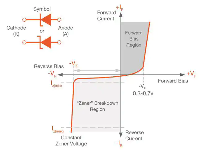
A zener diode is either forward biased (0.7V) or reverse biased (Vz)
If the battery discharges to the point were Vbatt=Vz (ie; 2.8V), then Vbatt-VBase=2.8V-0.7V=2.1V
2.1V < Vz,
so the zener will not conduct because there is not enough voltage to reverse bias it.
It stops conducting when the reverse voltage is less than the avalanche breadown voltage.
see attached.
Note the 0V/0 current point is the intersection of the x & y axis.
You can see that if the voltage is less than the knee voltage, it will not conduct.
This is clearly shown from the graph.
@OP,
FYI,
Since the zener voltage is not an exact value, if the transistor is still slightly on (VR is NOT 0V,
you can do one of two things.
.1. add a bleed resistor from base go GND.
2. choose a lower voltage zener
What this means is that you may need to calibrate the circuit using these two methods
The way to determine that the transistor is actually off is to measure the base voltage for
< 0.4V.
It would be usefull for you to create an Excell table that cross references VBase with VR,
so by measuring the VR, you can look up what VBase is so while you're calibrating it you can check
one or the other to see if the zener has shut off.
My feeling is that 2.8V might be on the high side. You may want lower that to 2.2V for the zener voltage.
Do some testing . I would definitely add the bleed resistor , (1k ) first.