Hey,
I'm trying to use the PS2X library to interface a ps2 controller with my Arduino to control some motors. However, I'm using a motor shield due to the power the motors need. As most of the digital pins are being used and i wanted to know if it is possible to use the analog pins on the Arduino Uno instead of the digital pins?
So far I've tried standard methods of selecting analog pins (A0, A1, ect ect).
Here's a small snippet of example code:
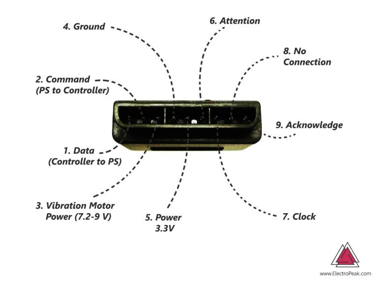
error = ps2x.config_gamepad(A5,A1,A3,A0, true, true); //GamePad(clock, command, attention, data, Pressures?, Rumble?)
Thanks in advance!
Edit:
The full code I’m using is just the same as the example provided by the library itself. as seen below.
#include <PS2X_lib.h>

PS2X ps2x;

//right now, the library does NOT support hot-pluggable controllers, meaning
//you must always either restart your Arduino after you connect the controller,
//or call config_gamepad(pins) again after connecting the controller.

int error = 0;
byte type = 0;
byte vibrate = 0;

void setup(){
 Serial.begin(57600);


 error = ps2x.config_gamepad(A5,A1,A3,A0, true, false);   //GamePad(clock, command, attention, data, Pressures?, Rumble?)

 if(error == 0){
   Serial.println("Found Controller, configured successful");
   Serial.println("Try out all the buttons, X will vibrate the controller, faster as you press harder;");
  Serial.println("holding L1 or R1 will print out the analog stick values.");
  Serial.println("Go to www.billporter.info for updates and to report bugs.");
 }

  else if(error == 1)
   Serial.println("No controller found, check wiring, see readme.txt to enable debug. visit www.billporter.info for troubleshooting tips");

  else if(error == 2)
   Serial.println("Controller found but not accepting commands. see readme.txt to enable debug. Visit www.billporter.info for troubleshooting tips");

  else if(error == 3)
   Serial.println("Controller refusing to enter Pressures mode, may not support it. ");

   type = ps2x.readType();
     switch(type) {
       case 0:
        Serial.println("Unknown Controller type");
       break;
       case 1:
        Serial.println("DualShock Controller Found");
       break;
       case 2:
         Serial.println("GuitarHero Controller Found");
       break;
     }

}

void loop(){
   /* You must Read Gamepad to get new values
   Read GamePad and set vibration values
   ps2x.read_gamepad(small motor on/off, larger motor strenght from 0-255)
   if you don't enable the rumble, use ps2x.read_gamepad(); with no values

   you should call this at least once a second
   */

 if(error == 1)
  return;

 if(type == 2){

   ps2x.read_gamepad();          //read controller

   if(ps2x.ButtonPressed(GREEN_FRET))
     Serial.println("Green Fret Pressed");
   if(ps2x.ButtonPressed(RED_FRET))
     Serial.println("Red Fret Pressed");
   if(ps2x.ButtonPressed(YELLOW_FRET))
     Serial.println("Yellow Fret Pressed");
   if(ps2x.ButtonPressed(BLUE_FRET))
     Serial.println("Blue Fret Pressed");
   if(ps2x.ButtonPressed(ORANGE_FRET))
     Serial.println("Orange Fret Pressed");


    if(ps2x.ButtonPressed(STAR_POWER))
     Serial.println("Star Power Command");

    if(ps2x.Button(UP_STRUM))          //will be TRUE as long as button is pressed
     Serial.println("Up Strum");
    if(ps2x.Button(DOWN_STRUM))
     Serial.println("DOWN Strum");


    if(ps2x.Button(PSB_START))                   //will be TRUE as long as button is pressed
         Serial.println("Start is being held");
    if(ps2x.Button(PSB_SELECT))
         Serial.println("Select is being held");


    if(ps2x.Button(ORANGE_FRET)) // print stick value IF TRUE
    {
        Serial.print("Wammy Bar Position:");
        Serial.println(ps2x.Analog(WHAMMY_BAR), DEC);
    }
 }

 else { //DualShock Controller

    ps2x.read_gamepad(false, vibrate);          //read controller and set large motor to spin at 'vibrate' speed

    if(ps2x.Button(PSB_START))                   //will be TRUE as long as button is pressed
         Serial.println("Start is being held");
    if(ps2x.Button(PSB_SELECT))
         Serial.println("Select is being held");


     if(ps2x.Button(PSB_PAD_UP)) {         //will be TRUE as long as button is pressed
       Serial.print("Up held this hard: ");
       Serial.println(ps2x.Analog(PSAB_PAD_UP), DEC);
      }
      if(ps2x.Button(PSB_PAD_RIGHT)){
       Serial.print("Right held this hard: ");
        Serial.println(ps2x.Analog(PSAB_PAD_RIGHT), DEC);
      }
      if(ps2x.Button(PSB_PAD_LEFT)){
       Serial.print("LEFT held this hard: ");
        Serial.println(ps2x.Analog(PSAB_PAD_LEFT), DEC);
      }
      if(ps2x.Button(PSB_PAD_DOWN)){
       Serial.print("DOWN held this hard: ");
     Serial.println(ps2x.Analog(PSAB_PAD_DOWN), DEC);
      }


      vibrate = ps2x.Analog(PSAB_BLUE);        //this will set the large motor vibrate speed based on
                                              //how hard you press the blue (X) button

    if (ps2x.NewButtonState())               //will be TRUE if any button changes state (on to off, or off to on)
    {
        if(ps2x.Button(PSB_L3))
         Serial.println("L3 pressed");
        if(ps2x.Button(PSB_R3))
         Serial.println("R3 pressed");
        if(ps2x.Button(PSB_L2))
         Serial.println("L2 pressed");
        if(ps2x.Button(PSB_R2))
         Serial.println("R2 pressed");
        if(ps2x.Button(PSB_GREEN))
         Serial.println("Triangle pressed");

    }


    if(ps2x.ButtonPressed(PSB_RED))             //will be TRUE if button was JUST pressed
         Serial.println("Circle just pressed");

    if(ps2x.ButtonReleased(PSB_PINK))             //will be TRUE if button was JUST released
         Serial.println("Square just released");

    if(ps2x.NewButtonState(PSB_BLUE))            //will be TRUE if button was JUST pressed OR released
         Serial.println("X just changed");


    if(ps2x.Button(PSB_L1) || ps2x.Button(PSB_R1)) // print stick values if either is TRUE
    {
        Serial.print("Stick Values:");
        Serial.print(ps2x.Analog(PSS_LY), DEC); //Left stick, Y axis. Other options: LX, RY, RX
        Serial.print(",");
        Serial.print(ps2x.Analog(PSS_LX), DEC);
        Serial.print(",");
        Serial.print(ps2x.Analog(PSS_RY), DEC);
        Serial.print(",");
        Serial.println(ps2x.Analog(PSS_RX), DEC);
    }


 }


 delay(50);

}
I’m new to arduino so I don’t exactly know what changes need to be made other than the obvious fact that the pin layout needs to be changed.
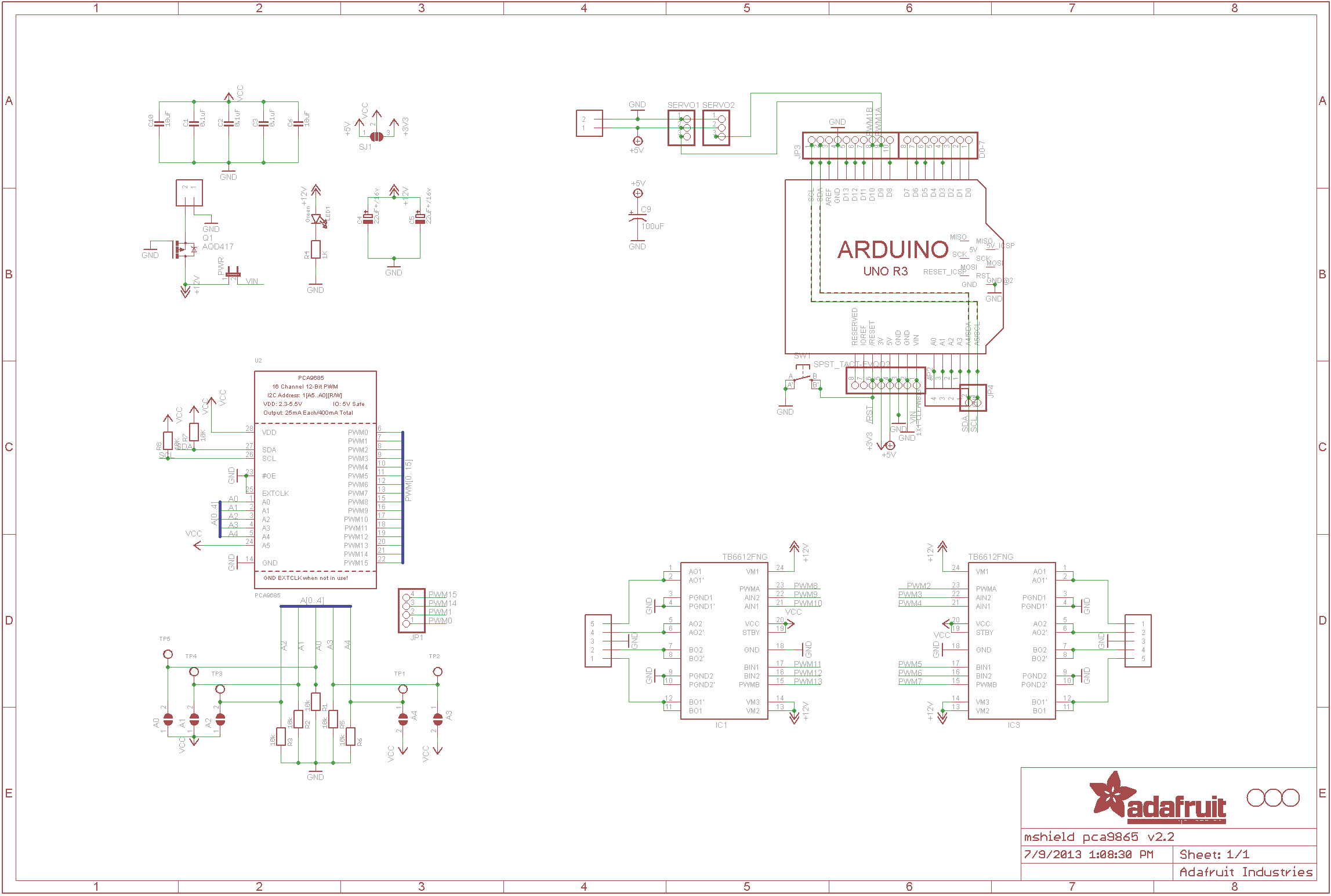
Im using an adafruit motor shield: from the manual i can see that pins 11,3,5,6 are used for the motor controller connections, pins 9 and 10 are for implementing 2 servo's. Pin 12 is the latch, pin 4 is for clock, pin 8 is for data and D7 is for enable?
When providing power to the ps2 receiver i am able to identify that the controller does successfully pair as the LED on the receiver suggests, but the code does not recognise that a controller has been connected or "paired".