Hi,
Ive just been reading how to do this through the forum and would like to confirm I have my ideas correct.
My project is to use 8 bright white LEDs as IR transmitters for beam break project. I have 2 arduinos. A nano to drive the 8 emitters on its own 5v power source - and an uno 4 ft away connecting the eight IR Receivers - on its own 5v power source.
I need to drive the 8 LED's at 38KHz for my TSP58038 receivers to detect.My plan is for the nano to send a continous burst across the 4ft opening
these White LED's have a forward voltage 3.2v, but a typical of 4v @20ma. this is the test sketch i've been practicing with - from just the one arduino.
#include <IRremote.h>

#define PIN_IR 3
#define PIN_DETECT 2
#define PIN_STATUS 13

IRsend irsend;
void setup()
{
  Serial.begin(9600);
  pinMode(PIN_DETECT, INPUT);
  pinMode(PIN_STATUS, OUTPUT);
  irsend.enableIROut(38);
  irsend.mark(0);
}

void loop() {
  digitalWrite(PIN_STATUS, !digitalRead(PIN_DETECT));
}
the problem is - that the irRemote.h lib only uses pin 3 to send 38khz . I have 8 leds and all those spare pins to use on the nano!
Can somebody advise me how to do this using the spare pins i have on the nano? (its only use is as an emitter).
I have found this pic from another post and I understand how this setup would work.
Im just interested in how to pulse each LED attached to a separate pin on the nano at 5v .
thanks
the picture failed to upload- but it was the one in this post
http://forum.arduino.cc/index.php?topic=278913.0
My project is to use 8 bright white LEDs as IR transmitters for beam break project
OK stop right there, that is not going to work. The IR receiver has a filter designed to block white light. You need IR LEDs.
the problem is - that the irRemote.h lib only uses pin 3 to send 38khz .
Why is that a problem? You need to send the same thing to each LED so simply wire a transistor's base through a resistor and drive all 8 IR LEDs ( each with it's own resistor ) to be switched with this transistor. It is by far the simplest way of doing things.
OK stop right there, that is not going to work. The IR receiver has a filter designed to block white light. You need IR LEDs.
Well I was having a few problems with distance.... I was advised by another forum user that these would work but max distance I have achieved is about 50cm. I bought tsal6200 ir senders anyway for full project.
I have some FAIRCHILD SEMICONDUCTOR BS170 N CHANNEL MOSFET http://uk.farnell.com/webapp/wcs/stores/servlet/ProductDisplay?catalogId=15001&langId=44&urlRequestType=Base&partNumber=1017687&storeId=10151. Any good for what you suggest?
They are not much good. You need 10V to turn them on and when you do the on resistance is up to 5 ohms!
Look for a FET that is described as logic level.
I was advised by another forum user that these would work
You won't get crap advice here. If any is given there are lots of real engineers that will jump on it.
for my TSP58038 receivers to detect
Got a link to a data sheet on that?
The only one I know of that will work as a light barrier is the TSOP4038.
http://www.vishay.com/docs/82479/tssp58038.pdf
Thanks for the help mike.
I've tested the tssp58038 with one white led at about 20cm distance on continuous 38khz pulse and it works fine.measures high when light beam break, low when light on.
Thanks. Initially you said:-
I need to drive the 8 LED's at 38KHz for my TSP58038 receivers to detect
Where as in fact you have a TSSP58038, the lack of an 's' foils any google search.
That looks fine but make sure you have the resistor and capacitor on the Vs line like it shows on page 1 otherwise it might not work correctly.
The key phrase here is the :-
It can receive continuous 38 kHz signals
thanks for the help grumpy mike.
transistor bc337 ok in the setup below? http://www.farnell.com/datasheets/1673712.pdf. Just found on another post someone using a 2200ohm resistor on the base.... dont understand why or how that is calculated using the spec sheet.
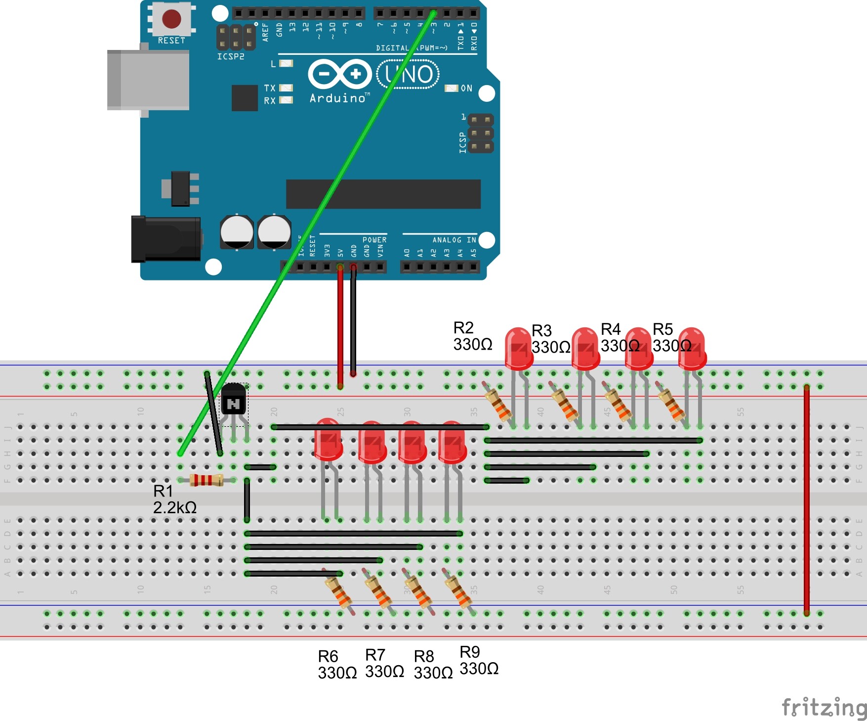
my first attempt at using fritzing software..... the IR emitters are TSAL 6200's. http://www.vishay.com/docs/81010/tsal6200.pdf
Ive gone for about 11milliamps on each of them in parallel which should be more than enough for 4ft gap. If one fails the others will still work. Frwd V is 1.35v each . 5v- 1.35 = 3.65. 3.65/330 = 11milliamps.
I hope thats right....
my first attempt at using fritzing software
I would recommend you make it your last, it produces useless results like that you posted. No good for doing anything. If you want to communicate your design to others the use a proper schematic.
.... dont understand why or how that is calculated using the spec sheet.
Take the load in the collector, say 8 * 11 mA = 88mA
Divide it by the minimum gain given in the data sheet, this is 100. So you need 0.88 mA down the base.
So with 5V - 0.7V = 4.3V from the pin this and 1mA base current then the base resistor should be 4.3K, double the base current for a bit of margin ans 2K2 sounds about right.