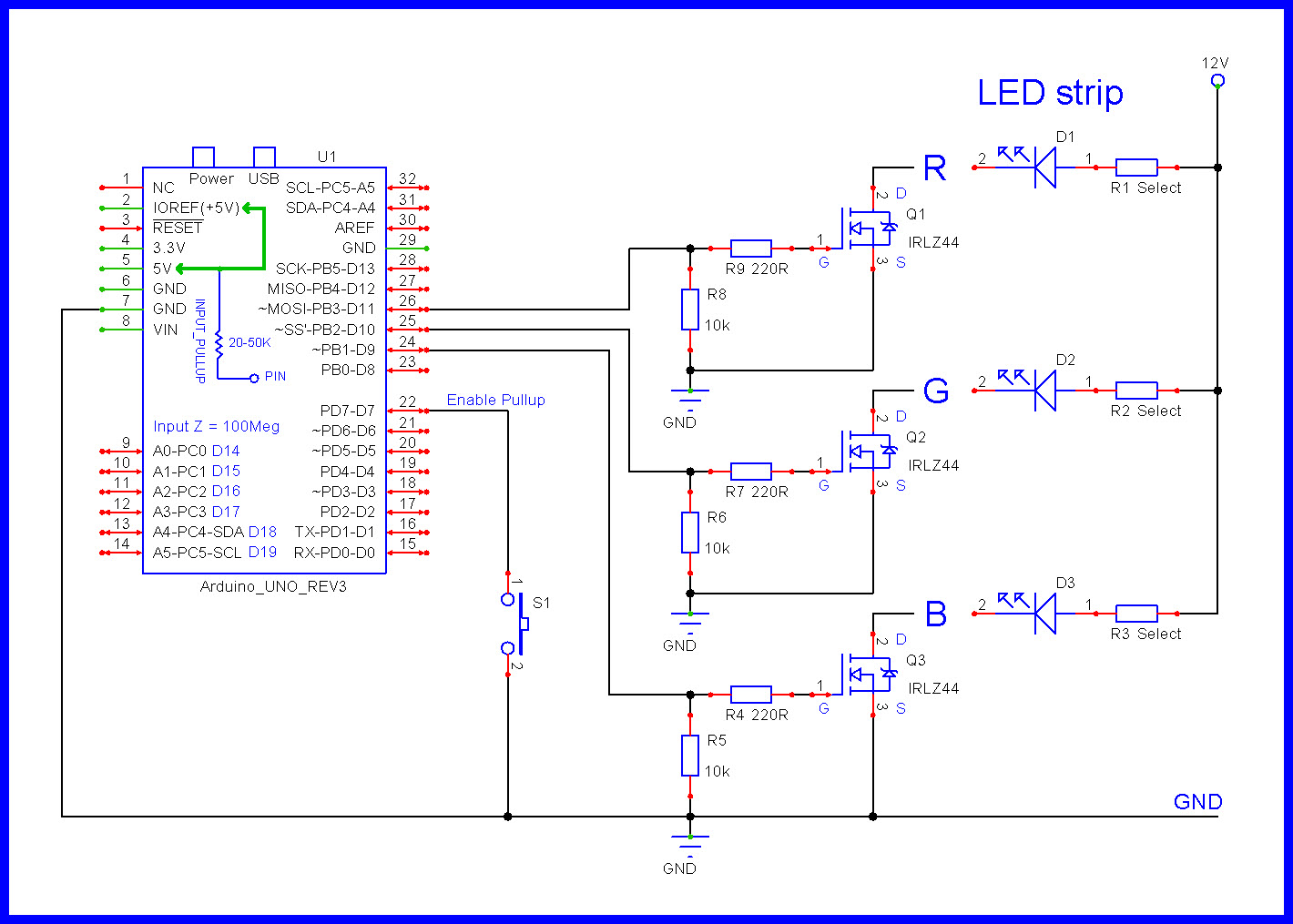
I am having trouble connecting a push button to my arduino nano without it interfering with my power supplie. The project is very simple. While I push the button, the RGB led strip turns on and when I release the button the led turns off. It all works fine while plugged in my laptop but when I connect it to a 9V battery via the VIN and GND the led strips never turns off and I cant figure out where to connect the button for it to work properly. Here is the code and a schematic of my circuit I took from this website https://www.instructables.com/Driving-RGB-LED-strips-off-an-Arduino/#discuss
my button is currently plugged into D7 and the ground next to the VIN
int bLed = 9;
int gLed = 10;
int rLed = 11;

int buttonPin = 7;
int buttonVal;

int dt = 800;

void setup() {

  pinMode(buttonPin, INPUT);

  pinMode(bLed, OUTPUT);
  pinMode(gLed, OUTPUT);
  pinMode(bLed, OUTPUT);

  digitalWrite(buttonPin, HIGH);

  Serial.begin(9600);

}

void loop() {

  buttonVal = digitalRead(buttonPin);

  while (buttonVal == 1) {

    buttonVal = digitalRead(buttonPin);

    analogWrite(bLed, 255);
    analogWrite(gLed, 255);
    analogWrite(rLed, 255);

    Serial.println(buttonVal);

  }

  analogWrite(bLed, 0);
  analogWrite(gLed, 0);
  analogWrite(rLed, 0);

  Serial.println(buttonVal);


}
Instructables are crap. Never use then unless you know more that the author and can spot his mistakes.
Can you show a photograph of how you have wired the button in the circuit. I bet it is not like you described, it looks like it is putting a short across the power supply.
thx for the tip I tried using INPUT_PULLUP but I still have the same problem, it works very well when plugged into my laptop via the micro USB then when I disconnect it and plug in my 9V battery it turns on when I push the button and never turns off
Unfortunately, I do not have a DMM, when I print the value they come out right but the arduino is plugged into the serial port of the computer. as soon as I disconnect it, it stops working properly. Do you think I should consider connecting a pull up resistor ?
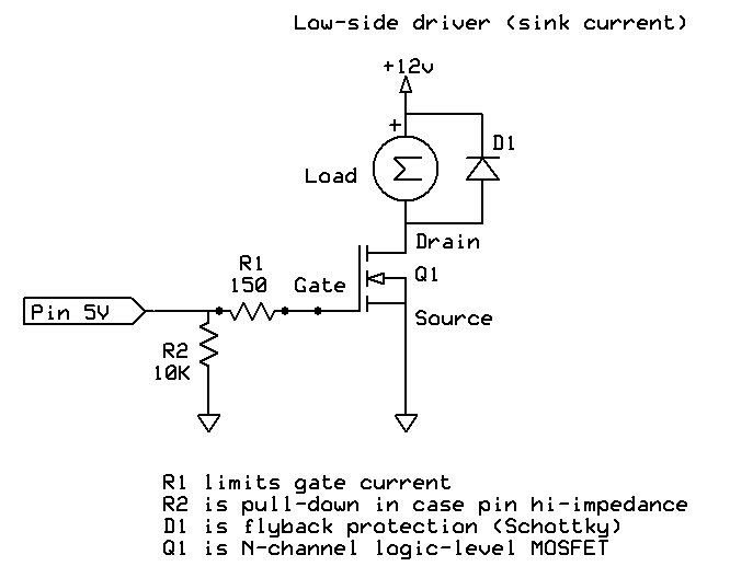
I made a mistake, I am actually using logic level IRLZ44 , I looked up the wrong data sheet. I am trying to add a pull-up resistor like shown on the schematic you offered but I am having trouble. the S3 circuit only includes a single LED so I am unsure of how to hook it up. I tried my best to wire it properly but I cant seem to figure it out. My guess is that the problem comes from the wiring of the button and not the program nor the transistor but I could be wrong, I dont have alot of experience with this.
My guess is that you have got the wiring to to power wrong. There is no reason why this should not work when powered by a battery, unless it is not wired correctly.
You did not answer about the type of 9V battery you have. Please tell us.
Use a 5 V power supply - a USB "phone charger" is generally inexpensive and available. If you connect it to the USB port, that will be exactly the same as powering it from the laptop, but a better way is to connect the regulated 5 V to the "Vcc" pin (and of course, ground).
What is most peculiar is your reluctance to confess what it is you actually mean by a "9V battery"!
I am was using a pp3 9V battery but I realise this wasnt an appropriated power source. Although by using the Vcc Pin it seems to work just fine !! thanks for the help, I will use a usb charger like recommended.