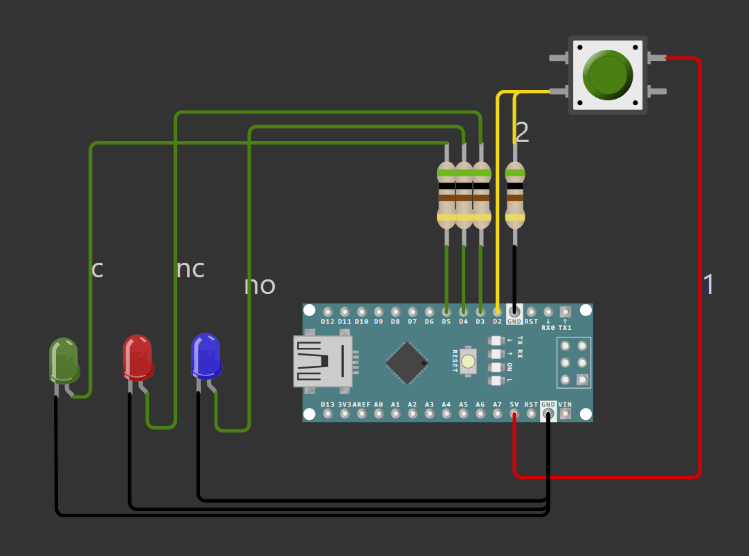
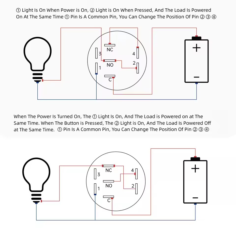
I am incredibly new to using Arduino, and I have no idea how to wire the pushbutton that I was given. Currently, I see 5 wires coming out of the pushbutton, one connected to each of the following, 1, 2, nc, no and c. Attached is my code and a diagram of how I have the breadboard currently wired.
  const int button = 2;
  const int r = 3;
  const int b = 4;
  const int g = 5;

  void setup() {
    pinMode(button, INPUT);
    pinMode(r, OUTPUT);
    pinMode(b, OUTPUT);
    pinMode(g, OUTPUT);
    Serial.begin(115200);
    digitalWrite(b, HIGH); // set pushbutton to blue
    digitalWrite(r, LOW);
    digitalWrite(g, LOW);
  }

  void loop() {
    int reading = digitalRead(button); // get button state
    if (reading == 0){ // if button is pressed
      digitalWrite(b, LOW);
      digitalWrite(r, HIGH);
    }
  }
Also you need to add some delay, otherwise the code will just loop as fast as it can = you will see all three LEDs lit since the human eye cannot keep up with the rapid changes.
Edit: "loop as fast as it can" while you press the button.
so just to clarify, for the button, one side should be GND with a resistor, and the other should just be a cable to digital2?
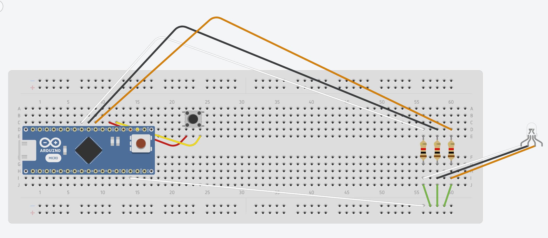
edit: I'm attaching a photo of my current breadboard as well as a diagram of the board, though I can't find the pushbutton on Tinkercad, so I just put in a button and an led light. The actual button and rbg light are just cables coming from the rbgpushbutton in the photo.
The resistor's function is supplied internally by the microprocessor, that's what INPUT_PULLUP does; but now that means the pin reads HIGH normally and LOW when pressed.
Gotcha thank you, would you have any idea why my still isn't doing anything when pressed? My wiring is now the exact same as the diagram shown above, and my code is above as well.
Edit: Currently the button glows at a low level red, regardless of me setting the following in code,
is looking for a pulled-up button to become pressed.
Your diagram shows a pulled down (with a resistor) switch, which would read HIGH when pressed.
So I can't tell what code you are running (post your latest) and how you are wiring the pushbutton.
We have said over and over:
Put the switch between ground and the input pin. No resistor. Use pin mode INPUT_PULLUP.
void loop() {
int reading = digitalRead(button); // get button state
if (reading == LOW){ // if button is pressed
digitalWrite(b, LOW);
digitalWrite(r, HIGH);
}
}
But... once those digitalWrite statements execute, nothin will ever be written differently, so whatever they did (turn off blue and turn on red) will stay done.
BTW have you tested your LED by connecting the anodes directly to 5 volts (using the same resistors you have at the cathodes) to see that thwey do in fact work and are in the circuit correctly?
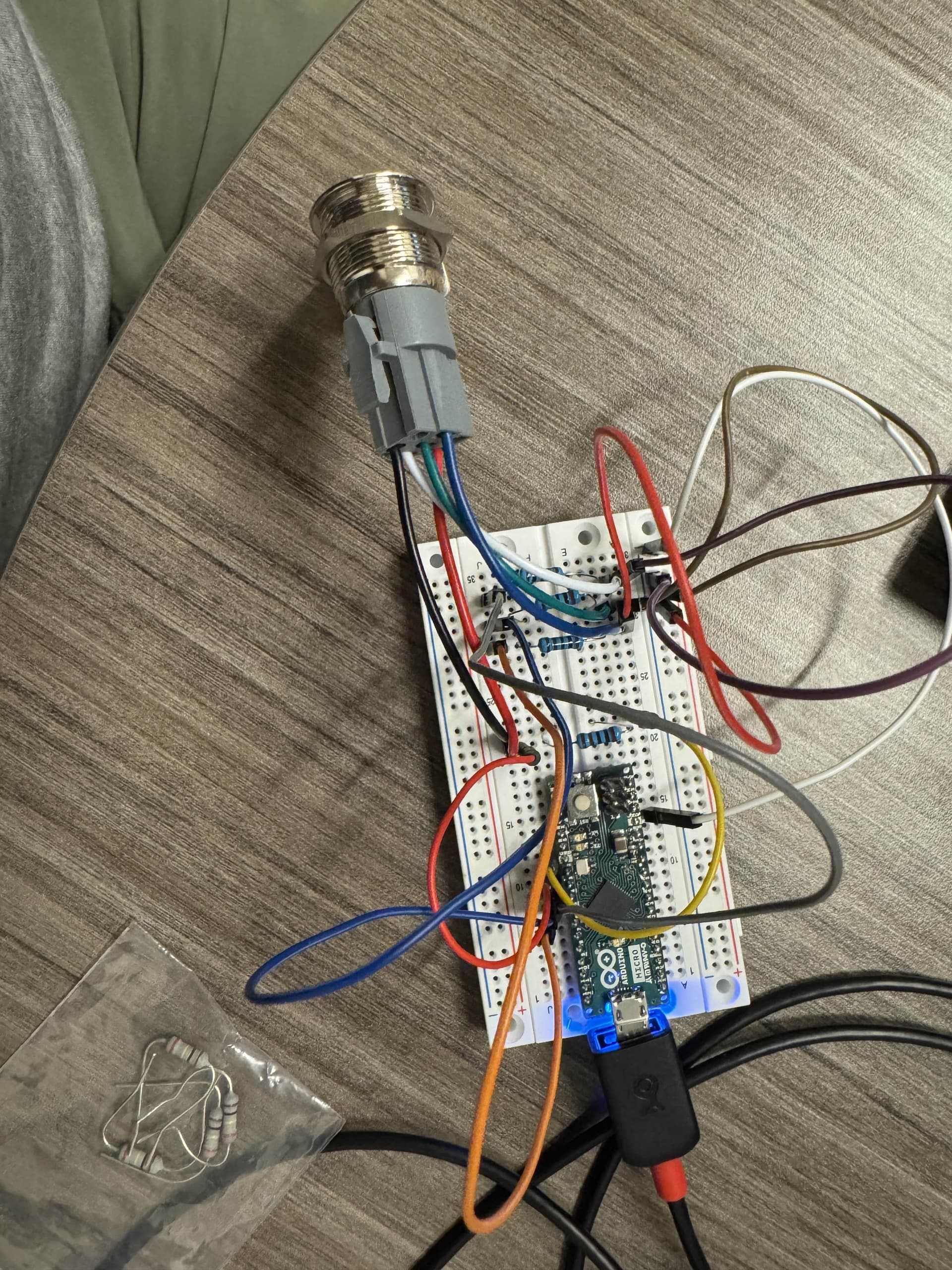
Thank you for the response, I changed the two pins to the button earlier to get rid of the resistor and used INPUT_PULLUP, but didn't say anything in the thread sorry. This is a photo of my current breadboard, along with my code.
const int button = 2;
const int r = 3;
const int b = 4;
const int g = 5;
void setup() {
  pinMode(button, INPUT_PULLUP);
  pinMode(r, OUTPUT);
  pinMode(b, OUTPUT);
  pinMode(g, OUTPUT);
  Serial.begin(115200);
  digitalWrite(b, LOW);
  digitalWrite(r, LOW);
  digitalWrite(g, LOW);
}
void loop() {
int reading = digitalRead(button); // get button state
if (reading == HIGH){
Serial.print("High");
digitalWrite(r, LOW);
digitalWrite(b, HIGH);
delay(1000);
}
else if (reading == LOW){
Serial.print("Low");
digitalWrite(r, HIGH);
digitalWrite(b, LOW);
delay(1000);
}
}
If the wiring is unclear, I can send another photo, but it should be the same as the tinkercad diagram I sent out earlier. Also I have not tested the LED's by the method you suggested, again, this is my first Arduino project so I didn't even think to do something like that, I'll test it now. Thank you again for the response.
It will only print high, even when I press the button, or hold it down. And it only ever shows red, even when I plug the anodes directly into 5v. Do you think it's a problem with the button? Or something with my resistors, maybe? Thanks again for the help.
That's one possibility, but usually it's we humans that makes mistakes. Do you have a multimeter? I would test the button with that. Strip away as much as possible and test from the ground and up.
Btw, you've done good by using Serial.print, it's an excellent tool.
Gotcha, thank you, and sorry for my inexperience this is my first project with anything EE related. So then for testing the button and the LEDs, where would I position the black and red terminal?