Hi, I have NTC100k thermistor and REXC100 pid controller, do you think I can use arduino to read the thermistor and output PWM as volatage to simulate thermocouple that is expected by the pid controller?
Yes, I expect that would work. You need an appropriate R/C filter. It's likely that the PID controller doesn't sample the thermocouple very rapidly, in which case it should work out OK with judiciously selected R and C values even at the 'default Arduino' PWM frequency of around 1kHz (not sure which Arduino board you're using).
I'd also pass the voltage through a simple voltage divider so it's scaled down to an appropriate range; e.g. for a K-type thermocouple, the signal range is only about 19mV (0.019V) for a 0-450C temperature (differential) range.
If you don't mind my asking - what are you trying to do? Keep in mind that trying to trick existing equipment into working with false/manipulated values doesn't always work out very well. There may be a better solution to whatever problem you're working on.
I think he needs the opposite; it looks like he wants to basically mimic a thermocouple using an Arduino.
I think he wants both... 
Doesn't look like it to me; it seems he wants to use an NTC (100k) as the sensing element and then use its readings (perhaps with some manipulations) to 'spoof' a thermocouple for the PID controller. Maybe @icmb can clarify.
Reading a 100k NTC can be done with just an additional resistor; if he intends to read out an actual thermocouple instead, the interfacing will evidently have to be different.
I agree!
Yes, I have mahor Extruder which has NTC integrated but the pid controller wants thermocouple. So i want the arduino to just convert the readings to the controller. I dont want to controll the heating element with arduino and relay because its not accurate.
You will be introducing a bazillion errors trying to emulate a thermocouple with an arduino.
You can run a pid controller on an arduino.
There's nothing about an Arduino that makes it inherently less accurate than the PID you've got. As @jim-p says, you can run a PID on Arduino just fine. If it's inaccurate, this is due to a faulty system design and that needs to be addressed. It would be a better solution than the somewhat clumsy, roundabout way that you're about to try now - which also involves the risk of stability problems and the certainty of higher system complexity.

If you think it could work then try it and see. Personally I don't think it will.
Exactly what accuracy do you need?
+/-1 deg C. +/-0.1 deg C?
Why not buy yourself a thermocouple?
At five to ten $/£/€ each, they are cheaper than the Arduino you are going to use.
I know you are reffering to doing the controling with arduino, I know its possible and Im afraid Im gonna have to do it that way, but its way more complicated than just using existing industrial controller, because I need to be able to change the wanted temperature whenever I want since its for 3d printing extruder which can do up to 300 celsia. I will need to use lcd and encoder for the controling and all that put in some box so it looks presentable. Also thanks guys for the help, I really appreciate it
I think it will be much more complicated than you imagine. Once you get into the code and hardware involved I think you will see that it's not an easy task for a beginner.
What REXC100 controller do you have? Some take RTDs

What extruder do you have?
This Mahon extruder doesn't look terribly integrated:

From the pics on the site, I'd guess one could fit a thermocouple or PT100 into the thermistor hole. You could at least measure the thermistor assembly.
Thats smart suggestion, i will look into that, ntc100k is 3mm in diameter and pt100 4mm so in cant fit. By integrated i meant its meant to be there but yes I can take it out, theoreticly i could make the hole bigger if necesery
These are 2mm od.
2mm K type thermocouple

As a matter of interest I decided to try and use an Ardunio Uno R3 to simulate a type K thermocouple.
I don't have a PID controller, but do have a multimeter which has a thermocouple input.
I built a circuit with a low-pass filter to convert a PWM output of the Arduino Uno into a DC voltage. I added an attenuator to reduce the 0 - 5V output down to 0 - 5mV - a range that would be suitable to simulate a thermocouple.

I chose 0 - 5mV after consulting this Type K Thermocouple Table, which indicates that 5mV corresponds to a temperature difference of just over 120°C.
I wrote some code to step a PWM output through various duty cycles from 0% to 100%.
int outputPin = 9;
int outVal = 0;
unsigned long previousMillis = 0;
const long interval = 5000;

void setup() {
  pinMode(outputPin, OUTPUT);
  Serial.begin(9600);
}

void loop() {
  unsigned long currentMillis = millis();
  if (currentMillis - previousMillis >= interval) {
    previousMillis = previousMillis + interval;

    analogWrite(outputPin, outVal);
    Serial.println(outVal);
    outVal = outVal + 5;
    if (outVal > 255) {
      while (1) {}
    }
  }
}
Here are the results:


There is an offset of around 30°C in the results due to the multimeter's cold junction compensation.
I also wrote some code to send SCPI commands to the multimeter, so that I could record the output for all 256 values of PWM duty cycle.
#include <SPI.h>
#include <Ethernet.h>

unsigned long previousMillis = 0;
const long interval = 10000;
int outPin = 9;
byte outVal = 0;

// Enter a MAC address and IP address for your Arduino
byte mac[] = { 0xA8, 0x61, 0x0A, 0xAE, 0x0B, 0xB5 };
IPAddress ip(192, 168, 0, 10);                          // desired Arduino IP address
IPAddress server(192, 168, 0, 8);                       // IP address of the Multimeter

EthernetClient client;

void setup() {

  // Start the Ethernet connection:
  Ethernet.begin(mac, ip);
  // Open serial communications and wait for port to open:
  Serial.begin(9600);
  pinMode(outPin, OUTPUT);
  analogWrite(outPin, outVal);

  // Give the Ethernet shield a second to initialize:
  delay(1000);
  Serial.println("connecting...");

  // Connect to the DMM:
  if (client.connect(server, 5025)) { // Port 5025 is commonly used for SCPI
    Serial.println("connected");
    // Send an SCPI command to the instrument:
    client.println("*IDN?");
  } else if (client.connect(server, 5555)) { // Port 5555 is used for SCPI by Rigol
    Serial.println("connected");
    // Send an SCPI command to the instrument:
    client.println("*IDN?");
  }  else {
    // If you didn't get a connection to the server:
    Serial.println("connection failed");
  }
  delay(1000);
  while (client.available()) {
    char c = client.read();
    Serial.print(c);
    // (100);
  }
  previousMillis = millis();
   client.println("read?");
}

void loop() {

  unsigned long currentMillis = millis();
  if (currentMillis - previousMillis >= interval) {
    previousMillis = currentMillis;

    Serial.print(outVal);
    Serial.print(", ");
    client.println("read?");

    // If there are incoming bytes available from the DMM:
    while (client.available()) {
      char c = client.read();
      Serial.print(c);
    }

    // set next duty cycle:
    outVal = outVal + 1;
    analogWrite(outPin, outVal);

    // If the server disconnected, stop the client:
    if (!client.connected()) {
      Serial.println();
      Serial.println("disconnecting.");
      client.stop();
      // Do nothing more:
      while (true);
    }
  }
}
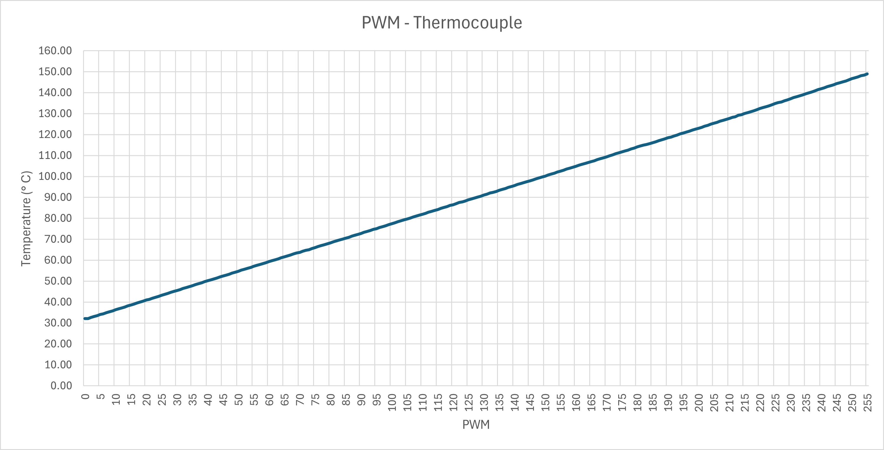
PWM - Temperature.txt (2.8 KB)
This shows that it might be possible to use an Arduino to simulate a thermocouple connected to a PID controller.