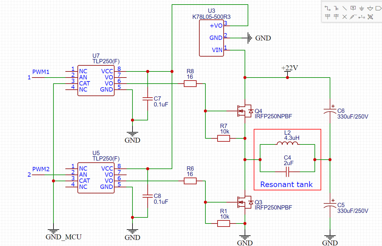
Hello! I am building an induction heater device controlled by half-bridge driver. I've already successfully tested the Mazilli ZVS flyback driver, and now I would like to achieve heating control with a new scheme. Driver schematics will be shown below. MOSFETs are controlled by optocouplers which receive PWM signals from a microcontroller. PWM signals must have 53 KHz frequency and 180-degree phase shift. I would like to use my Arduino Nano to achieve this. For PWM I am planning to use pins 3 and 11 and therefore mess with Timer2. For now, I just want to create a code for testing the driver with an adjustable duty cycle by encoder rotation. I used Nano before with a MAX6675 scheme and thermocouple, SSD1306 OLED display and rotary encoder and I would like to keep them. My current questions are:
-
Is it suitable to use Arduino Nano's timer2 to generate two PMW signals with desired frequency and phase shift? Link1 - according to this topic I have to use timer1 to achieve that. Another topic with Mega2560 and only phase shift looks useful too link2.
-
Which PWM mode is preferable for my task?
-
Is it correct that the duty cycle can only be within the 0-50% range for half-bridge driver control?
I will be glad if you could suggest a better approach if there is any.
Some initial code without encoder part:
#define PWM1_PIN 3
#define PWM2_PIN 11

void setup() {
  pinMode(PWM1_PIN, OUTPUT);
  pinMode(PWM2_PIN, OUTPUT);

  // Phase shift
  TCCR2A |= (1 << COM2B0);

 // Code to set PWM frequency
 //

  // Initial PWM duty cycle for both signals:
  int dutyCycle = 0;  // can be only from 0  to 127 ?
  OCR2A = (OCR2A * dutyCycle) / 255;
  OCR2B = (OCR2B * dutyCycle) / 255;
}

void loop() {
  // Some control logic with encoder
}
Thank you in advance!

