i have a graduation Project to make 2 parallel buck choppers and control the mosfets by arduino, i should send 2 PWM signals to mosfet gates with 30KHz and variable duty cycle between 10 to 90 % and with 180 phase shift between them or 16.67 microseconds, i tried some codes with gives me output signal with frequency 34KHZ but the duty cycle of the 2 signals is not right and i dont know where is the problem so can you help me ?
#define PIN1 3 // Define pin for first PWM signal
#define PIN2 5 // Define pin for second PWM signal
#define DUTY_CYCLE 10 // Define duty cycle in percentage
const long PERIOD = 33; // Timer period for 30 kHz frequency in microseconds
volatile bool flag = false; // Flag to alternate between pins
void setup() {
pinMode(PIN1, OUTPUT);
pinMode(PIN2, OUTPUT);
// Configure Timer 1 for Fast PWM mode with TOP value of PERIOD-1
TCCR1A = _BV(WGM11);
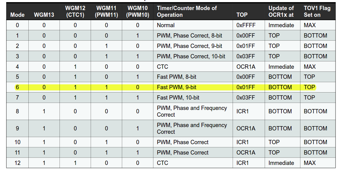
TCCR1B = _BV(WGM12) | _BV(WGM13) | _BV(CS10); // Set WGM13 for mode 15 (Fast PWM, TOP = ICR1)
ICR1 = PERIOD - 1; // Set TOP value for 30 kHz frequency
const int dutyValue = (DUTY_CYCLE * ICR1) / 100;
OCR1A = dutyValue - 1; // Set duty cycle for pin 1 (initially)
OCR1B = dutyValue - 1; // Set duty cycle for pin 2 (initially)
TIMSK1 |= _BV(TOIE1); // Enable timer overflow interrupt
}
void loop() {
// No code needed in the main loop, everything handled in the interrupt
}
ISR(TIMER1_OVF_vect) {
// Toggle flag on each overflow
flag = !flag;
// Update duty cycle based on flag and pin
if (flag) {
digitalWrite(PIN1, LOW);
digitalWrite(PIN2, HIGH);
} else {
digitalWrite(PIN1, HIGH);
digitalWrite(PIN2, LOW);
}
}
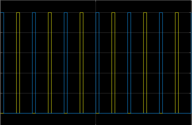
The code in the ISR makes one pin high and the other low, or the other way around. It is never going to give you the desired output. That they don't switch at the same time is because you use two slow digitalWrite() statements, rather than a single fast PORT call which can set two pins at the same time (as long as they're in the same PORT).
The "desired output" graph shows two independent signals: both pins can be low (or, presumably, high) at the same time.
The easiest way to do this:
use one of the PWM pins that's on Timer1 (I'll leave looking up which ones that are to you)
use one of the PWM pins that's on Timer2
set Timer1 to overflow at 256
set TCNT1 to 0 and TCNT2 to 128 to have a 90° phase shift between the two outputs
set duty cycle of each as needed.
I prefer those two timers so not to have to mess about with the Timer0 settings, which controls the millis() and micros() timers. If you don't need those timers of course you can also use Timer0 for this.
i agree with you that the problem in the digitalWrite() section, Can you help me modifying the code and set the timers well ? also i need the phase shift to be 180 not 90
Check the datasheet for the PWM settings of the timers (as you've been doing already), set them to your liking. You use OCRxA or OCRxB to set the duty cycle. The datasheet reading I leave to you, I don't have it all memorised either. It's all explained quite extensively there.
Then you offset one of the timers by 128:
TCNT1 = 0;
TCNT2 = 128;
In two lines immediately following one another.
That should give two PWM signals offset by 180°. Pins are set HIGH when TCNT1 resp TCNT2 overflow to 0 (so halfway the cycle of the other), and set to LOW at a point in time depending on what value you set the respective OCRxx registers to. OCRxx = 25 for 10% duty cycle, or 230 for 90% duty cycle, or well anything between 0 and 255.
Using phase and frequency correct PWM mode the channel pulses occur centered around counter overflow. Invert one channel output and both signals are off by 180°. You only have to adjust the duty cycle of the inverted channel to 100-x % for identical pulse width.
i tried another code with timer 0 and trying to adjust OCR0A&B values to change the freq of the pulses and i am using proteus simulator the frequency is not changed whatever i do and const at 62KHz
#define dute_cycle 40

void setup() {
  // Set pins 5 and 6 as output
  pinMode(5, OUTPUT);
  pinMode(6, OUTPUT);

  // Configure Timer0 for Fast PWM mode
  TCCR0A = (1 << COM0A1) | (1 << COM0B1) | (1 << WGM01) | (1 << WGM00);
  TCCR0B = (1 << CS00);  // No prescaler

  // Set TOP value for desired frequency (30 kHz)
  // Formula: TOP = (F_CPU / (N * desired frequency)) - 1
  // For Arduino Nano (16 MHz), N = 1
  OCR0A = 105;  // TOP value for pin 5 (16 MHz / (1 * 30 kHz) - 1)
  OCR0B = 105;  // TOP value for pin 6 (16 MHz / (1 * 30 kHz) - 1)
}

void loop() {
  // Adjust duty cycle if needed
  // Example: 50% duty cycle for both pins
  analogWrite(5, (dute_cycle * 255) / 100);
  analogWrite(6, 128);
}
It’s an 8 bit timer, so it counts from 0 to 255.
You have no prescaler so 16Mhz/256 = 62.5kHz
The next lowest frequency you can get with timer 0 is 7.812.5 Hz