PWM glitch (ATTiny)

Hi,

I'm having fun programming LED scripts on an ATTiny, and I am observing a very strange behaviour that boils down to this simple test case:

void setup() {
  pinMode(0, OUTPUT);     
}

void loop() {
  for (int i = 0; i <= 255; i++) {
    analogWrite(0, i);
    delay(10);
  }
  analogWrite(0, 0);
  delay(1000);    
}

As you can see, the output (connected to a simple LED) ramps up from 0 to 100% in about 2.5s, then drops abruptly and leaves the led off for 1s, and does that all over again.

However, running this code causes a visible flash of random duration at the beginning of the ramp: See this video.

Conditions:

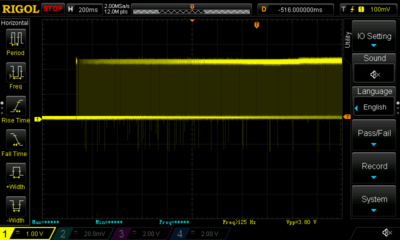
The scope shows that when starting the ramp loop, we get a first PWM cycle with a variable (and sometimes very high) duty cycle:


I thought maybe calling analogWrite with a value of 0 triggers a special behaviour (like turning PWM off without resetting some registers), which would cause the first "non-zero" analogWrite at the beginning of the ramp to start with the previous settings, so I tried to add an "analogWrite(0, 1)" just after the "for" loop, but nothing changed.

Then I added a 1ms delay between that "analogWrite(0, 1)" and "analogWrite(0,0)". On the scope, I can clearly see one PWM period with a very small duty-cycle at the end of the ramp, but still, the flash happens. Here you can see the "analogWrite(0,1)" in action during 1ms:

Then I increased that delay to 10ms, and then only the flash disappeared completely: Here is the end and the beginning of the ramp:


Is that a known issue ?
Any idea of why that happens and how to get rid of that "flash" in a clean way ?

Best regards,

Vicne

1 Like

Hi,

Replying to self ;-):

Vicne:
I thought maybe calling analogWrite with a value of 0 triggers a special behaviour (like turning PWM off without resetting some registers)

Well, that guess was correct. analogWrite() is implemented both in standard Arduino distribution as well as in arduino tiny cores as follows:

void analogWrite(uint8_t pin, int val)
{
   // [...]
   pinMode(pin, OUTPUT);
   if (val == 0)
   {
      digitalWrite(pin, LOW);
   }
   else if (val == 255)
   {
      digitalWrite(pin, HIGH);
   }
   else
   {
      // ...
   }

(the tests in tiny cores are "<= 0" and ">=255", but basically it's the same logic)

Could someone please confirm if this behaviour is also visible on a genuine Arduino (I don't have one, sorry) ? If not, I'll file a bug in the arduino tiny cores project

Thanks for your attention,

Vicne

1 Like

Hi, all,

Today, I changed the arduino-tiny cores library and removed the test above so that in analogwrite() never falls back to digitalwrite() when value is 0 or 255, and the result is perfect. I am filing the issue to the arduino-tiny project.

Now the question remains: is this behaviour specific to ATTiny or is it also the case on a ATMega.

Could someone please upload the above 10-line sketch to an UNO and see if there is a random flash there too ?

Thanks

Vicne

1 Like

sketch_mar01a.ino: In function ‘void analogWrite(uint8_t, int)’:
sketch_mar01a.ino:16:4: error: expected ‘}’ at end of input

do i a } on the end
then

core.a(main.cpp.o): In function main': /usr/share/arduino/hardware/arduino/cores/arduino/main.cpp:11: undefined reference to setup'
/usr/share/arduino/hardware/arduino/cores/arduino/main.cpp:14: undefined reference to `loop'
collect2: error: ld returned 1 exit status

the first code in your topic ,works good

Hi, gonnie08,

Thank you very much for taking the time to test.

gonnie08:
sketch_mar01a.ino: In function ‘void analogWrite(uint8_t, int)’:
sketch_mar01a.ino:16:4: error: expected ‘}’ at end of input

That is probably with the snippet of code in the second post.
This was not a real code to test, just a summary of what I found in the libraries.
It is not correct code so it cannot run. That is normal.

the first code in your topic ,works good

Great, that is the one to focus on.
And do you see a very small "flash" on the led, like in my video ?

Thanks again.

Vicne

1 Like

Hi Vicne,

I don't have an Uno but I do have a Nano 3, which is also atmeg328.

Not sure if I'm seeing your glitch or not, I might just be imagining it (having watched your vid) or maybe it is there but less noticeable because of the higher clock speed. What speed was your '85 running at? I don't have a scope.

I used pin 5, led via 330R to ground.

Paul

Hi, Paul, and thanks for testing too.

PaulRB:
Not sure if I'm seeing your glitch or not, I might just be imagining it (having watched your vid) or maybe it is there but less noticeable because of the higher clock speed.

Yes, I admit that if it's there, it's nowhere as noticeable as in my case.

What speed was your '85 running at?

My Attiny85 was running at 8MHz on its internal oscillator, but I'm not sure it has an influence.

If the problem does not happen on ATMega, then most probably it's a bug in the arduino-tiny cores...

In the meantime, I ordered a Leonardo so hopefully I can confirm that.

Thanks again,

Kind regards,

Vicne

1 Like

@Vicne, would you mind testing this change...

The original code of interest...
https://code.google.com/p/arduino-tiny/source/browse/cores/tiny/wiring_analog.c#64
https://code.google.com/p/arduino-tiny/source/browse/cores/tiny/wiring_digital.c#65

The new code (may not compile)...

wiring_analog.c ...

// Right now, PWM output only works on the pins with
// hardware support.  These are defined in the appropriate
// pins_*.c file.  For the rest of the pins, we default
// to digital output.
void analogWrite(uint8_t pin, int val)
{
  // We need to make sure the PWM output is enabled for those pins
  // that support it, as we turn it off when digitally reading or
  // writing with them.  Also, make sure the pin is in output mode
  // for consistenty with Wiring, which doesn't require a pinMode
  // call for the analog output pins.
  pinMode(pin, OUTPUT);

  if (val <= 0)
  {
    digitalWrite(pin, LOW);
  }
  else if (val >= 255)
  {
    digitalWrite(pin, HIGH);
  }
  else
  {
    #if CORE_PWM_COUNT >= 1
      if ( pin == CORE_PWM0_PIN )
      {
        Pwm0_SetOutputCompareMatch( val );
        Pwm0_SetCompareOutputMode( Pwm0_Clear );
      }
      else
    #endif

    #if CORE_PWM_COUNT >= 2
      if ( pin == CORE_PWM1_PIN )
      {
        Pwm1_SetOutputCompareMatch( val );
        Pwm1_SetCompareOutputMode( Pwm1_Clear );
      }
      else
    #endif

    #if CORE_PWM_COUNT >= 3
      if ( pin == CORE_PWM2_PIN )
      {
        Pwm2_SetOutputCompareMatch( val );
        Pwm2_SetCompareOutputMode( Pwm2_Clear );
      }
      else
    #endif

    #if CORE_PWM_COUNT >= 4
      if ( pin == CORE_PWM3_PIN )
      {
        Pwm3_SetOutputCompareMatch( val );
        Pwm3_SetCompareOutputMode( Pwm3_Clear );
      }
      else
    #endif

    #if CORE_PWM_COUNT >= 5
    #error Only 4 PWM pins are supported.  Add more conditions.
    #endif

    {
      if (val < 128)
      {
        digitalWrite(pin, LOW);
      }
      else
      {
        digitalWrite(pin, HIGH);
      }
    }

  }
}

wiring_digital.c ...

// Forcing this inline keeps the callers from having to push their own stuff
// on the stack. It is a good performance win and only takes 1 more byte per
// user than calling. (It will take more bytes on the 168.)
//
// But shouldn't this be moved into pinMode? Seems silly to check and do on
// each digitalread or write.
//
__attribute__((always_inline)) static inline void turnOffPWM( uint8_t pin )
{
  #if CORE_PWM_COUNT >= 1
    if ( pin == CORE_PWM0_PIN )
    {
      Pwm0_SetCompareOutputMode( Pwm0_Disconnected );
      Pwm0_SetOutputCompareMatch( 0 );
    }
    else
  #endif

  #if CORE_PWM_COUNT >= 2
    if ( pin == CORE_PWM1_PIN )
    {
      Pwm1_SetCompareOutputMode( Pwm1_Disconnected );
      Pwm1_SetOutputCompareMatch( 0 );
    }
    else
  #endif

  #if CORE_PWM_COUNT >= 3
    if ( pin == CORE_PWM2_PIN )
    {
      Pwm2_SetCompareOutputMode( Pwm2_Disconnected );
      Pwm2_SetOutputCompareMatch( 0 );
    }
    else
  #endif

  #if CORE_PWM_COUNT >= 4
    if ( pin == CORE_PWM3_PIN )
    {
      Pwm3_SetCompareOutputMode( Pwm3_Disconnected );
      Pwm3_SetOutputCompareMatch( 0 );
    }
    else
  #endif

  #if CORE_PWM_COUNT >= 5
  #error Only 4 PWM pins are supported.  Add more conditions.
  #endif

    {
    }

}

Hi, Coding,

Thanks for your help.

I just tested your proposed changes (they compiled first time), but unfortunately, they don't seem to improve the situation (see captured trace).

Do you know what's the rationale behind turning PWM off and switching to digitalWrite() if the code calls analogWrite() with 0 or 255 ?

I guess it's probably to reduce power consumption or to free up unused resources (timers ?), but wouldn't it be better to leave that responsibility to the programmer to call digitalWrite() in those cases ?

Clearly, sticking to using a PWM output with a duty cycle of 0 or 100% solves the issue...

Kind regards,

Vicne

1 Like

Hi Vicne,

Vicne:
Do you know what's the rationale behind turning PWM off and switching to digitalWrite() if the code calls analogWrite() with 0 or 255 ?

Prevent the digital I/O commands from becoming modal (e.g. enablePwm, disablePwm, setPwmOutput). Reduce the amount of stuff people have to learn before being productive.

Clearly, sticking to using a PWM output with a duty cycle of 0 or 100% solves the issue...

There are two problems with that solution: 1. There is a narrow spike at 0%; the output is not completely off. 2. There is no way to turn off the PWM driver. If the user wants to also use the pin as an input they're stuffed.

In any case, it is what it is. Version 1 of the Tiny Core is meant to be "highly compatible". The Arduino / AVR core does it that way so version 1 will do it that way. However, if we find something that works better, I will submit a bug report on the Arduino core.

I just tested your proposed changes (they compiled first time), but unfortunately, they don't seem to improve the situation (see captured trace).

I'll take another pass at it today.

Hi Vicne,

Please confirm you replacedturnOffPWMinwiring_digital.cwith the code above.

Yes I did.
I guess the makefile takes care of recompiling those files when they change, right ?

Kind regards,

Vicne

1 Like

Sure simplicity is key indeed.

There are two problems with that solution: 1. There is a narrow spike at 0%; the output is not completely off.

Well, having googled for PWM glitch first, I found several people mentioning that issue on other architectures indeed, but having tried myself on the ATtiny85 (commenting out the two fallbacks to digitalWrite()), my scope didn't trigger on any spike when pwm was set to 0...

  1. There is no way to turn off the PWM driver. If the user wants to also use the pin as an input they're stuffed.

Well, not sure I understand... If a user simply calls digitalWrite(pin, 0) instead of analogWrite(pin,0), he'll get the exact same result as today.
To the contrary, with the current implementation, there is no way one can really set the PWM duty-cycle to zero (or nearly zero).

In any case, it is what it is. Version 1 of the Tiny Core is meant to be "highly compatible". The Arduino / AVR core does it that way so version 1 will do it that way. However, if we find something that works better, I will submit a bug report on the Arduino core.

Well, I understand that "analogWrite()" shoudl remain as it is today (even if buggy) if you think it would break backwards compatibility, but maybe adding a "pureAnalogWrite()" would be the solution ?

Something along the lines of :

void analogWrite(uint8_t pin, int val)
{
   // [...]
   pinMode(pin, OUTPUT);
   if (val == 0)
   {
      digitalWrite(pin, LOW);
   }
   else if (val == 255)
   {
      digitalWrite(pin, HIGH);
   }
   else
   {
      pureAnalogWrite(pin, val);
   }
}

void pureAnalogWrite(uint8_t pin, int val)
{
    #if CORE_PWM_COUNT >= 1
      if ( pin == CORE_PWM0_PIN )
      {
        Pwm0_SetCompareOutputMode( Pwm0_Clear );
        Pwm0_SetOutputCompareMatch( val );
      }
      else
    #endif

    [...]

}

Well, "pureAnalogWrite" may not be the best name, but you get my point :slight_smile:

What do you think ?

Kind regards,

Vicne

1 Like

Vicne:
I guess the makefile takes care of recompiling those files when they change, right ?

The IDE does.

Vicne:
...having tried myself on the ATtiny85 (commenting out the two fallbacks to digitalWrite()), my scope didn't trigger on any spike when pwm was set to 0...

Fast has a spike. Phase-correct does not.

I have been able to reproduce the problem on pin 9 of an Uno. At first blush it appears the shadow register is not updated when the output driver is disabled. In case anyone wants to follow along, this is the test code for the Uno; the board should only have a USB connection...

const uint8_t OutPin = 9;

static uint8_t Value;

static unsigned long HighCount;
static unsigned long LowCount;
static unsigned long TotalCount;

void setup( void )
{
  Serial.begin( 115200 );
  Serial.println( F( "Go..." ) );
  Value = 255;
}

void loop( void )
{
  uint8_t Save1;
  uint8_t Save2;

  ++Value;
  HighCount = 0;
  LowCount = 0;

  while ( TCNT1 == 0 );
  while ( TCNT1 != 0 );

  Save1 = OCR1A;
  analogWrite( OutPin, Value );
  Save2 = OCR1A;

  while ( TCNT1 == 0 )
  {
    if ( PINB & (1 << PINB1) )
    {
      ++HighCount;
    }
    else
    {
      ++LowCount;
    }
  }

  while ( TCNT1 != 0 )
  {
    if ( PINB & (1 << PINB1) )
    {
      ++HighCount;
    }
    else
    {
      ++LowCount;
    }
  }

  Serial.print( Value );
  Serial.write( '\t' );
  Serial.print( HighCount );
  Serial.write( '\t' );
  Serial.print( HighCount+LowCount );
  Serial.write( '\t' );
  Serial.print( Save1 );
  Serial.write( '\t' );
  Serial.print( Save2 );
  Serial.println();
//  delay( 100 );
  
  if ( (Value == 1) && (HighCount > 500) )
  {
    Serial.println( F( "Gotcha!" ) );
    while ( true );
  }

  if ( Value == 255 )
  {
    analogWrite( OutPin, 0 );
    delay( 1000 );
  }
}

Got it. The shadow output compare register is only updated while the output driver is enabled.

With the way the API works the only way to remove the glitch is to make analogWrite(P,0) and analogWrite(P,255) wait for one timer cycle to ensure the shadow register has been updated.

@Vicne, I cannot change Tiny Core 1 without introducing a side-effect (i.e. it will not longer be "highly compatible"). Changing the PWM functions has been discussed ad nauseum on the Developers List. The conclusion has consistently been to leave things the way they are. When I have time I will broach the subject yet again. In the meantime I suggest you plan to work around the problem.

const uint8_t OutPin = 9;

static uint8_t Value;

static unsigned long HighCount;
static unsigned long LowCount;
static unsigned long TotalCount;

void setup( void )
{
  Serial.begin( 115200 );
  Serial.println( F( "Go..." ) );
  Value = 255;
}

void loop( void )
{
  uint8_t Save1;
  uint8_t Save2;

  ++Value;
  HighCount = 0;
  LowCount = 0;

  while ( TCNT1 == 0 );
  while ( TCNT1 != 0 );

  Save1 = OCR1A;
  analogWrite( OutPin, Value );
  Save2 = OCR1A;

  while ( TCNT1 == 0 )
  {
    if ( PINB & (1 << PINB1) )
    {
      ++HighCount;
    }
    else
    {
      ++LowCount;
    }
  }

  while ( TCNT1 != 0 )
  {
    if ( PINB & (1 << PINB1) )
    {
      ++HighCount;
    }
    else
    {
      ++LowCount;
    }
  }

  Serial.print( Value );
  Serial.write( '\t' );
  Serial.print( HighCount );
  Serial.write( '\t' );
  Serial.print( HighCount+LowCount );
  Serial.write( '\t' );
  Serial.print( Save1 );
  Serial.write( '\t' );
  Serial.print( Save2 );
  Serial.println();
  
  if ( (Value == 1) && (HighCount > 500) )
  {
    Serial.println( F( "Gotcha!" ) );
    while ( true );
  }

  if ( Value == 255 )
  {
    // One more time around to update the shadow register
    OCR1A = 0;
    TCCR1A |= (1 <<COM1A1);
    while ( TCNT1 == 0 );
    while ( TCNT1 != 0 );

    analogWrite( OutPin, 0 );
    delay( 1000 );
  }
}

Hi, Coding,

Thanks first for your insightful help.

I see. Makes sense.

@Vicne, I cannot change Tiny Core 1 without introducing a side-effect (i.e. it will not longer be "highly compatible"). Changing the PWM functions has been discussed ad nauseum on the Developers List. The conclusion has consistently been to leave things the way they are. When I have time I will broach the subject yet again.

OK. If I understand correctly, it's not only a Tiny Core issue, if the UNO is also affected.
Does it change anything in the way the issue will be handled ? As I said, I already filed a bug on the Arduino Tiny project, but maybe it's not the best place if it's not Tiny specific...

In the meantime I suggest you plan to work around the problem.

Sure. However, would you be so kind as to give me an advice on the way to work around it in a relatively portable fashion ? I'd rather not make the fix attiny85-specific in case anybody wants to reuse my code on another chip.

Thanks very much.

Vicne

1 Like

Oh, and by the way, I tested the symmetric situation (slow ramp down, then sudden jump to 255 for one second, and repeat) and the very same behaviour is visible at the beginning of the ramp (see below).
I guess it makes sense according to your analysis.

I find it really strange that nobody noticed that before however... :slight_smile:

Kind regards,

Vicne

1 Like

very interesting post, thank you for highlighting it, and thank you for information on the effects/causes etc :slight_smile:

You are welcome.

Vicne:
OK. If I understand correctly, it's not only a Tiny Core issue, if the UNO is also affected.

Correct. The problem stems from a combination of the way the AVR hardware works and the way the two cores interact with the hardware.

However, would you be so kind as to give me an advice on the way to work around it in a relatively portable fashion ?

Without modifying both cores, the only way to make the code portable is to add a layer of insulation...

void analogWrite0( int value )
{
  if ( value <= 0 )
  {
    OCR0A = 0;
  }
  else if ( value >= 255 )
  {
    OCR0A = 255;
  }
  else
  {
    analogWrite( 0, value );
  }
}

Call analogWrite0 in setup with a value that is >= 1 and <= 254 to configure the pin for PWM then call analogWrite0 at will to set the value.

You will have to have a replacement for analogWriteX for each pin and each processor.