Hi,
I am "intermediate" at electronics I think, but am relatively new to Arduino.
I am building an Arduino-powered bench power supply from an ATX PSU. I have the PSU all sorted out, and I am now prototyping a variable 0-20 volt channel. I want to use a 3 pin optical rotary encoder as the knob, but that is not the problem.
I had the idea to use the PWM feature of Arduino to drive a transistor which has 12v externally hooked up to it. I am using a 2n2222 NPN transistor, and a low-pass filter with a 0.1 uF cap and a 2.7K ohm resistor. I hooked it all up with a 10k linear pot just for prototyping, and it's not working for some reason.
Here is the code:
int inputPin = A0;  // set input pin for the potentiometer
int inputValue = 0; // potentiometer input variable
int controlPin = 3; // set output pin

void setup() {
    // declare the ledPin as an OUTPUT:
    pinMode(controlPin, OUTPUT);
}

void loop() {
    // read the value from the potentiometer:
    inputValue = analogRead(inputPin);

    // send the square wave signal to the LED:
    analogWrite(controlPin, inputValue/4);
}
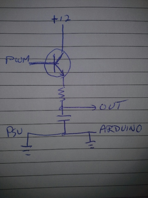
Can anybody help please? I attached a crappy drawing of my setup below.
I would put the design into SPICE if you do not have an o-scope. A good, free version is here http://www.falstad.com/circuit/
The standard components are pretty complete.
Your schematic is a little hard to read, but it looks like you have GND connected to the emitter of the transistor, to the top of the resistor, and to the bottom of the capacitor. If that's the way you have it, it will definitely not work. Could you supply a clearer schematic?
themacman33:
My main issue is tying the PSU and Arduino together.
That's not going to work at all. Your main issue is that every time the Arduino PWM pin goes high, the transistor will conduct, effectively shorting 12V to GND. Your Output line will never change, as the resistor/capacitor circuit goes from GND to GND.
Your transistor may well be toasted.
See attached for a possible schematic that should work.
See attached for a possible schematic that should work.
I dropped this into the simulator and it seems that the NPN never conducts with the circuit values provided earlier... and I added a 100 Ohm load resistor, but it really does not mapper if the transistor never biases forward.
But you guys can play around with the values... the .txt file will import the schema into falstad.
Does the code seem right? I tried out lar3ry's schematic, and I got an output from 0 v to 2.53v. This seems to be just the output from the Arduino. Is this code related? What should be my next step?
I am worried that I might accidentally short the 12v into the Arduino and damage it. Is there any risk of this? Should I add some protection diodes?
I have not even looked at the code! All I am doing is using a pulse generator to drive the base of the NPN. The simulator is showing the base is never being forward biased. Normally, I would expect a PNP for high-side switching. But, I'm not doing the design here... just commenting.
One basic problem: To conduct, the base of an NPN transistor must be more positive than the emitter by about 0.6V. That means that even with your circuit wired more correctly as lar3ry has it, the emitter will only rise to 5V - 0.6V or about 4.4V maximum.
BTW, no resistor between the Arduino pin and a transistor is a very bad idea.
Did you look at the links mrburnette gave for high side switching? The answer you seek is there.
Oh, thank you. I just misunderstood earlier.
I got the NPN based circuit to work, but it has a 50% voltage drop! likely attributed to the PWM code. I am now trying the PNP based circuit to see if it is more stable.
If I were doing this, I'd go the DAC route... hey, but that is just me. The links below are for your review- there may be some good takeaways, but I'm not going to spoon-feed you.
ATtiny based variable (stepped) supply:
Here is an article that uses an AVR and PWM to create a nice variable supply (sound familiar?):
Hopefully, with the material above you will be able to move forward.
When you have some time, read Electronics 2 paying careful attention to the term "saturation".
I did the attached circuit and it works, while somehow doubling the input voltage. Why is this?
Also, when I used a low-pass filter, the potentiometer suddenly seemed logarithmic, increasing slowly the first 3/4, and very rapidly the last 1/4. Any ideas? I need the low pass filter to make a steady voltage, not just PWM, right?
I am not using any wirewounds. 12v is coming from another PSU.
I retested the output, and it seems that my analog multimeter is displaying it at 30v when my digital says 11.5v. Weird.
I tried a 47uf cap and it totally wrecked the variability. It would start at 12v, and when I turned it down to 3v, it would take 15 minutes to drain.
15 minutes to drain... sure, because the PWM is only charging the capacitor, not draining it.
In fact, we're missing something here. If you run this circuit with the 0.1uF cap attached and with the only load being a 10M ohm input meter, you should be getting nearly 12V with any duty cycle above 0%. If it is 10% duty cycle, it is charging 10% of the time, and holding steady 90% of the time. But eventually it charges to 12V.