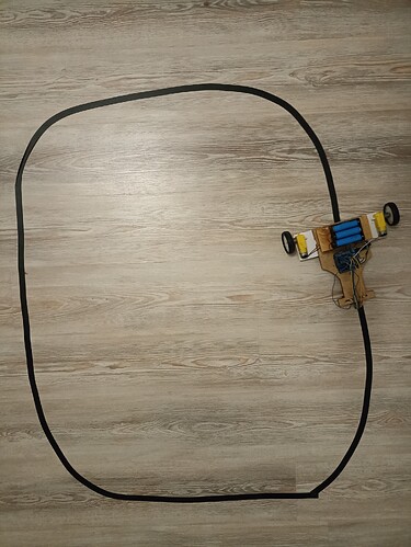
Hello!
I'm making line follower, it has to follow black line on grey wooden background:
problem is, that it follows wooden lines instead of tape
I've seen line follower, that follows tape on brown wooden background.
Here's my code:
#include <QTRSensors.h>
#include <Arduino.h>
#include <SoftwareSerial.h>


//Defning pins for motors
#define left_mtr_frwrd 7
#define left_mtr_bkwrd 6
#define right_mtr_frwrd 4
#define right_mtr_bkwrd 5

#define left_mtr_sped 9
#define right_mtr_sped 10

//define variables for qtr sensor array

QTRSensors qtr;

const uint8_t SensorCount = 6;
uint16_t sensorValues[SensorCount];


//define constants for PID

const double KP = 0.04;
const double KD = 0;

double lastError = 0;
int GOAL = 2500;
const unsigned char max_speed = 100;

void setup() {
  //Starting serial to exchange status with our PC
  Serial.begin(9600);

  qtr.setTypeAnalog();
  qtr.setSensorPins((const uint8_t[]){ A0, A1, A2, A3, A4, A5 }, SensorCount);
  qtr.setEmitterPin(2);

  delay(500);
  pinMode(LED_BUILTIN, OUTPUT);
  digitalWrite(LED_BUILTIN, HIGH);  // turn on Arduino's LED to indicate we are in calibration mode

  //turn motors on, so it can turn himself around to calibrate

  // analogRead() takes about 0.1 ms on an AVR.
  // 0.1 ms per sensor * 4 samples per sensor read (default) * 8 sensors
  // * 10 reads per calibrate() call = ~24 ms per calibrate() call.
  // Call calibrate() 400 times to make calibration take about 9.8 seconds.
  for (uint16_t i = 0; i < 400; i++) {
    qtr.calibrate();
  }
  digitalWrite(LED_BUILTIN, LOW);  // turn off Arduino's LED to indicate we are through with calibration


  for (uint8_t i = 0; i < SensorCount; i++) {
    Serial.print(qtr.calibrationOn.minimum[i]);
    Serial.print(' ');
  }
  Serial.println();

  // print the calibration maximum values measured when emitters were on
  for (uint8_t i = 0; i < SensorCount; i++) {
    Serial.print(qtr.calibrationOn.maximum[i]);
    Serial.print(' ');
  }
  Serial.println();
  Serial.println();
  delay(1000);

  motor(1, 0, 1, 0);
}

void loop() {
  // read calibrated sensor values and obtain a measure of the line position
  // from 0 to 5000 (for a white line, use readLineWhite() instead)
  uint16_t position = qtr.readLineBlack(sensorValues);

  //compute eerror
  int error = GOAL - position;

  //Compute motor adjustment
  int adjustment = (KP) * (error) + KD * (error - lastError);

  //Store error for next iteration

  lastError = error;

  //Adjust motors
  motor_speed(constrain((max_speed - adjustment), 0, max_speed), constrain((max_speed + adjustment), 0, max_speed));
}
And my functions:
// function to easily control motors; e.g. motor(1, 0, 1, 0); - forward

void motor( int left_frwrd, int left_bkwrd, int right_frwrd, int right_bkwrd) {
  digitalWrite(left_mtr_frwrd, left_frwrd);
  digitalWrite(left_mtr_bkwrd, left_bkwrd);
  digitalWrite(right_mtr_frwrd, right_frwrd);
  digitalWrite(right_mtr_bkwrd, left_bkwrd);
}

//function to easily control speed of motor

void motor_speed(int left_sped, int right_sped) {
  analogWrite(left_mtr_sped, left_sped);
  analogWrite(right_mtr_sped, right_sped);
}


void ir_status() {

  // print the sensor values as numbers from 0 to 1000, where 0 means maximum
  // reflectance and 1000 means minimum reflectance, followed by the line
  // position
  for (uint8_t i = 0; i < SensorCount; i++)
  {
    Serial.print(sensorValues[i]);
    Serial.print('\t');
  }
//  Serial.println(position);
}
thanks for your time
