In the comments of this page, someone mentioned that in their experience it's a good idea to use a relay in the circuit to prevent kickback current. As I have a spare relay module (Sainsmart 8 Channel DC 5V Relay Module), this seems like an approach worth considering.
If I were to use the Sainsmart relay module, would I still need to use a resistor, a transistor, and a diode? Or could I just wire the solenoid onto the relay module and have the relay simply act as a switch? When the relay would be thrown, it would provide current to the solenoid and have it engage.
The diode across the relay coil is there to absorb the kickback voltage that occurs when the solenoid is energized or de-energized. Even if you were to use a relay to drive the solenoid, the diode should still be placed across the solenoid to protect the relay (mechanical or solid state) from the high kickback voltage.
The diode across the relay coil is there to absorb the kickback voltage that occurs when the solenoid is energized or de-energized. Even if you were to use a relay to drive the solenoid, the diode should still be placed across the solenoid to protect the relay (mechanical or solid state) from the high kickback voltage.
I'm not following this. If you have a relay controlling a solenoid , then the solenoid is connected to the CONTACTS on the relay.
The relay coil itself is an inductor so of course requires a flyback diode, but since there is NO CONTINUITY between the SOLENOID
coil and the relay coil , I fail to see the connection between the flyback diode across the relay coil (to protect the transistor that sinks the relay coil current) and soloenoid, which is in no way connected to the relay coil since it is only connected to the contacts..
Can you help me understand your logic here ?
We both have enough experience with hardware that we don't need a schematic to visualize this but I just can't see your reasoning.
If the transistor were replaced by the relay the solenoid should have the diode across it to make the relay contacts last longer. The diode will eliminate contact arcing from the solenoid kickback voltage.
I thought that's what RC snubber circuits were used for. You explanation makes sense but it won't prevent contact arcing when opening the contacts with the load under power. because the diode is across the load and as the contacts separate the current causes arcing that continues until the contacts are far enough apart. A flyback diode is for back emf. The arcing I am referring to is the same arcing you see from a plug to a socket if you pull the plug of a fan or something that is on.
GroundFungus and Raschemmel: Thanks for the lively responses to my post. I've been focused on other things for the past few days so haven't had time to work on this.
Unlike both of you, I'm still very much a beginner in this field. So, I want to be sure exactly what is being recommended.
groundfungus:
the solenoid should have the diode across it
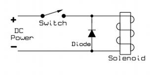
What is meant by "across it" ? Do you mean literally across the poles as shown in this diagram?
Would a 1N4007 Diode be suitable for placing across the solenoid?
raschemmel:
The arcing I am referring to is the same arcing you see from a plug to a socket if you pull the plug of a fan or something that is on.
Is there a way to protect against this? The solenoid will be triggered via the relays quite often (200 times per hour), so the arcing you are referring to could well become an issue. What would you recommend?
This is what is being discussed for diode, relays, and solenoid motor.
If you have a relay module, everything on the left side is taken care of in the module.
It's only the solenoid (which is just a coil of wire, like a motor) that you need to take of.
Use a diode that is rated for at least as much current as flows thru the solenoid when the relay contacts closed.
Crossroads, by the 'left side,' do you mean everything but the solenoid and the diode across the solenoid? (Please see my amended version of the pic you posted)
Also, with reference to my amended version of your pic, would this be the correct circuit for a solenoid? I just want to be sure as your original pic referenced either an LED or Motor in the file name.
(Sorry for these rather newbie questions)
Raschemmel: your links made for some interesting reading. The Red Lion RC snubber (XEB0471) snubber looks like a great solution, but I'm having no luck in finding this in Europe. Red Lion is calling this an arc suppressor. Is this component also known as a spark suppressor/spark quencher? The reason I ask is that I'm literally drawing a blank when searching at the big european electronic component distributors for this type of component. Is there an alternate name for an arc/spark suppressor/snubber?
In the USA that same resistor is sold at RadioShack. However the one in the link you posted is 22 ohms , you need 120 ohms as in the schematic of Reply#6. You could get by with 100 ohms but I wouldn't go lower than that. Anything between 100 and 150 is fine.


