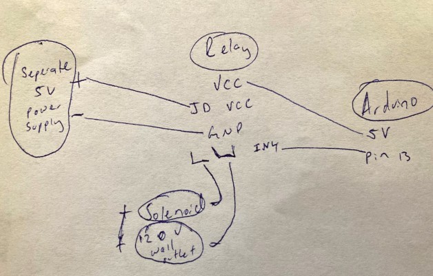
Hey all. I’m fairly new to this. I’m using an arduino to control a relay that activates a 12v solenoid valve. I will include my circuits below. The circuit works fine when the relay turns on, but as soon as it shuts off the code crashes. I’ve read about voltage spikes and snubber circuits. Can someone give me advice or a diagram on how to build one and where to put it in? Thanks in advance.

Welcome to the forum.
Can you give more information ?
Which Arduino board do you use, which relay module (with a link to where you bought it). Which solenoid is it ? Does it run at 120V AC ? What kind of separate power supply ? How is the Arduino powered ? and so on, and so on.
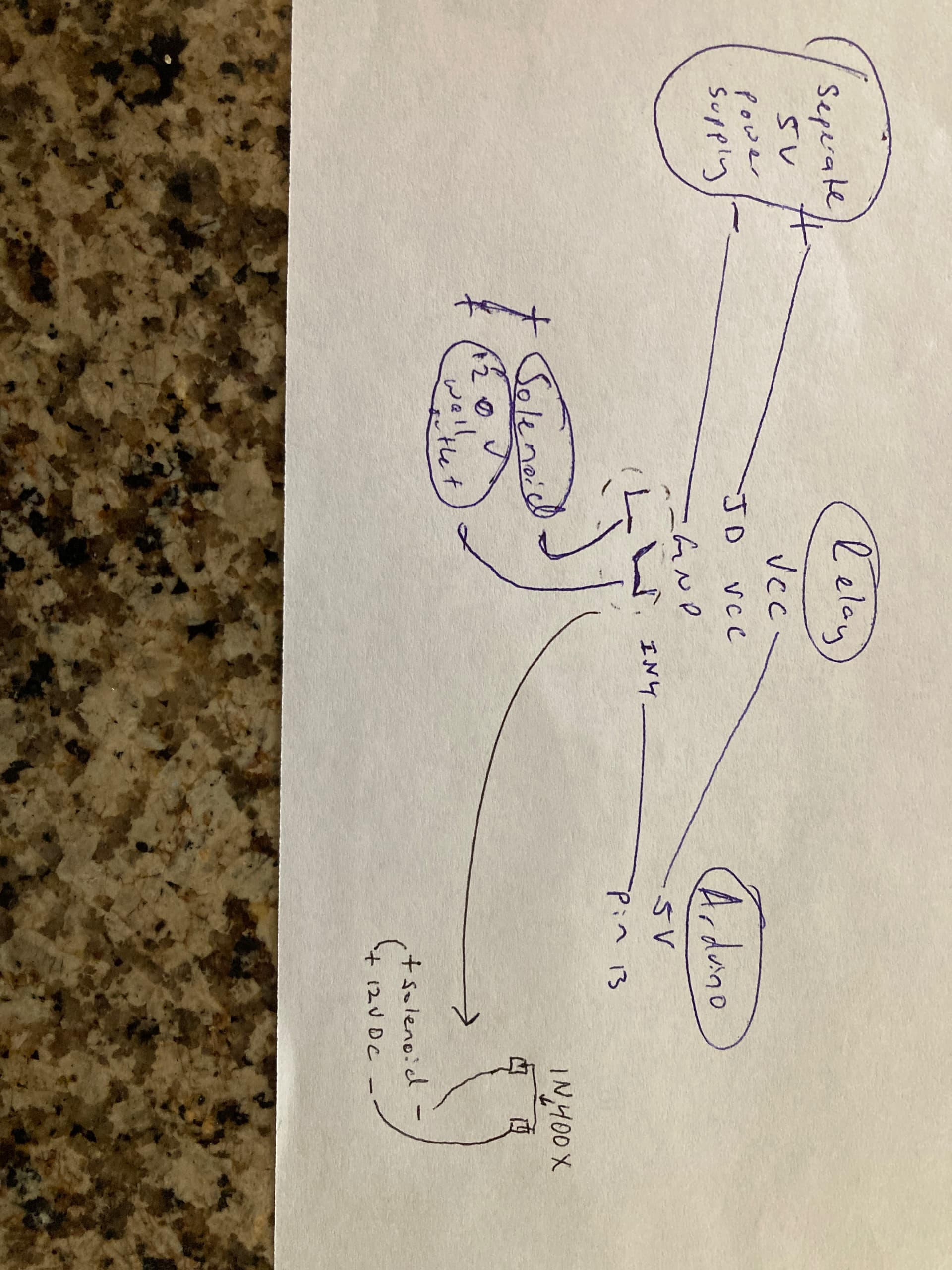
The picture rotated:
Typically, a diode is placed across the relay coil contacts.
Here is the link to the solenoid. It’s a 12V DC. I currently have an adapter plugged into a 120AC outlet that converts to 12vDC. Amazon.com
I’m using an arduino uno. The relay is https://www.amazon.com/SunFounder-Channel-Shield-Arduino-Raspberry/dp/B00E0NSORY/ref=mp_s_a_1_12?crid=TB52N0WUEMUT&keywords=relay+for+arduino&qid=1652998208&sprefix=relay+for+%2Caps%2C174&sr=8-12
The arduino is powered by a 9v dc power supply. However, it is also plugged into my computer via usb because I need it to relay information to my screen. The 5v power supply powering the relay is a seperate 5v dc power supply
What kind of diode would you use?
1n400x
The diode goes in BACKWARDS with the cathode connected to the high side. This is a shunt diode that will short out the inductive kick when the field collapses as the relay/solenoid turns OFF. This is the same principle that a car ignition operates off, the field collapses when the points OPEN, causing the spark to form. The diode prevents this.
Interesting. Is it possible for you to add to my diagram so I can be certain? How do I know if I’m connecting the cathode to the high side?
The relay you linked to is a 4 channel relay module. I am seeing a diode at the base of each relay labeled D1, D2, D3 and D4 so I am guessing those are flyback diodes. I would also guess the 4 pin chips are Opto Isolators. The relay module board is designed so it should not be a problem. You may want to consider diodes across your solenoids like a 1N4002.
Ron
If he's using a board then there shouldn't be a kickback issue. If it's a naked relay, then diodes are REQUIRED.
The band on the diode is the negative (cathode) end. On the schematic the band is the line and the positive (anode) is the Arrow shape (A for Anode) It should be connected across the relay coil like this schematic shows:

Schematic shows unmarked diode internal to module
This next type of relay card is a quad, others are very similar, has opto drivers and anti-kickback diodes (seen at lower edge of blue relay cube). If the relay is on a card it most likely HAS a diode. If its a "loose" relay, it NEEDS a diode.

@guywhobuilds, your topic has been moved to a more suitable location on the forum. Installation and Troubleshooting is not for problems with (nor for advise on) your project ![]() See About the Installation & Troubleshooting category.
See About the Installation & Troubleshooting category.
https://www.onsemi.com/pdf/datasheet/1n4001-d.pdf
Relay connections:

In the image you drew, you do not connect the GND of Arduino to the GND of the "separate power supply" for relay. Connecting two GNDs together.
It's not clear to who you are replying. But in the image of @JCA34F, the grounds should not be connected if one wants isolation. If @guywhobuilds uses the same modules, the GNDs should not be connected.