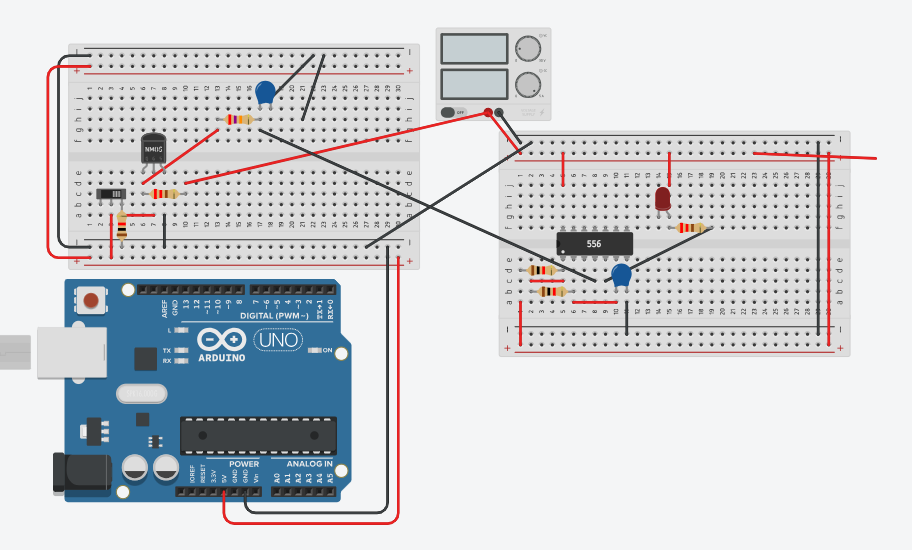
Hello, can somebody help me. I am trying to make a blinking light when my switch is off. When I switch back on, the led should continue to blink for 5 seconds. But, I'm facing a problem where my led does not turn off after 5 seconds when I switch it back on.
I was initially confused by what the function of the Arduino is, but I quickly saw that you are just using it to provide 5V to your breadboard. Are you powering the Arduino from its USB input? If so, in your position I'd be a little nervous about a short on the breadboard shorting the PC's USB 5V. It shouldn't do permanent damage. If you are powering the Uno from the barrel jack, you risk overheating the 5V regulator on the Arduino, again it shouldn't do any permanent damage. Even so, why not use an old 5V USB charger and a USB cable you can cut the other end off? Solder some pins to that end which will plug into the breadboard.
[Edit: Oh I just noticed this thing, is it a power supply providing 5V?

If so, why is the Arduino included in the diagram?]
What is this? I can't read the part number on it.

What you posted is a wiring diagram. Do you have a schematic that you could post?
Sure do. Thank you for replying. This is my circuit diagram. I am unable to make it to continue blink for only 5 seconds (or a few seconds) after i turn on the switch.

What code are you trying?
You have a floating gate on your MOSFET, when the switch is closed the MOSFET gate is connected to 5V, when the switch is open the gate is not connected to anything so is floating, which means the voltage on the gate is unknown and could be anything. Try a 10k resistor between the MOSFET gate and ground.
Your schematic shows you are using only one half of a 556 timer.
You need to use the second half of the 556 timer to generate a 5s pulse, that enables/disables the half that you are using to flash the LED.
Do u mean building a monostable timer on the other half?
Complementing @PerryBebbington's post, since the BS170 is a MOSFET, its gate acts like a capacitor, creating a short circuit when discharged!
You should add a series resistance with the gate to limit the current that could damage the transistor.
- A gate resistor is not necessary in this circuit.
- If the switch was replaced by a controller GPIO, a gate resistor would be added to limit the GPIO current to a safe GPIO level.
Thank you all for your comments, but my led still does not continue to blink after the switch is turned on. My idea is to let an RC circuit discharge the reset Pin when the switch is on so that the output is not low for a few seconds. But, I don't think my RC circuit is discharging as expected.
So can you post the schematic that you have modified from the comments you received and think it should work in a new post. In other words do not modify any other posts but post a fresh one.
So have you tried doing this? Because to me that sounds like just the thing you need to do.
1 Like