I just got pass this video : https://www.youtube.com/watch?v=LjpSkz5zfiA and I want to recreate it . I have an arduino uno 3 + the model relays shown in the video . but can't figure out how he simulate the touche on the screen
Hi, @yassine145287
Welcome to the forum.
Can you please tell us your electronics, programming, arduino, hardware experience?
Tom.. ![]()
![]()
![]()
![]()
See the large nuts on the sensor? He used a relay to switch a ground to those nuts. It is likely that is how he smashed his touch screen.
This video explains the process so much better, only he used coins in place of nuts.
")
1 Like
I have tried the coin trick but no resulat . I have an iphone 7 i don't know if this trick would work on it or if the problem is on my wiring
Well it is exactly the same thing as the nuts on the original video. You can see the relays on the two videos are the same.
It could be your wiring or it could be your ground environment to your phone or it could be your phone can't handle multiple touches.
Have you tried with just one coin or nut?
Have you tried connecting the ground you are using to simulate the touch to the outer case of your phone as well.
Or try connecting the ground you switch to the mains ground?
Make sure you are using the correct relay contacts as well.
what do you mean with "the outer case of your phone as well" ?
The as well bit means in addition to the other things that you can try.
The outer case of your phone could be connected to the ground that you switch.
I have noticed that on my iPad touching the back of it with my hands improves the touch performance over laying it down and just touching the screen.
I still face the same problem. IDK if you have the parts so that you can test it on your side
I only have an iPad and you can see from the two videos that it works on an iPad, I suspect the problem is with your phone. I don't even know what phone you have, but I don't have any phone with a touch screen.


Well it is a collection of photographs that are too blurred and too close up to be able to trace where any of the wires go so they are not too helpful.
When you say tested them how have you done that?
By slots do you mean connections?
The photos show nothing about any of the three connections being wired up to anything.
Do you here the relay clicking when you run the test circuit?
You might be being confused by the poor diagram in the video, this is it.

This is how the circuit should be wired.
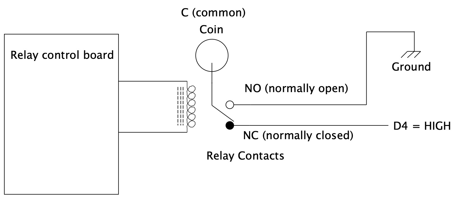
You need to use all three relay connections to make it work. When the relay is not being energised the coin is at the value given by D4, which should be a HIGH, this needs to be set up in the code. Then when the relay is energised the coin is connected to ground and the touch is simulated. The ground here should be the Arduino ground. As we have discussed before this could be other sorts of ground as well.
Actually I cant see why a relay is being used and it might work just by connecting D4 to the coin and switching that between HIGH and LOW. But I haven't tried this so I don't know if it works.
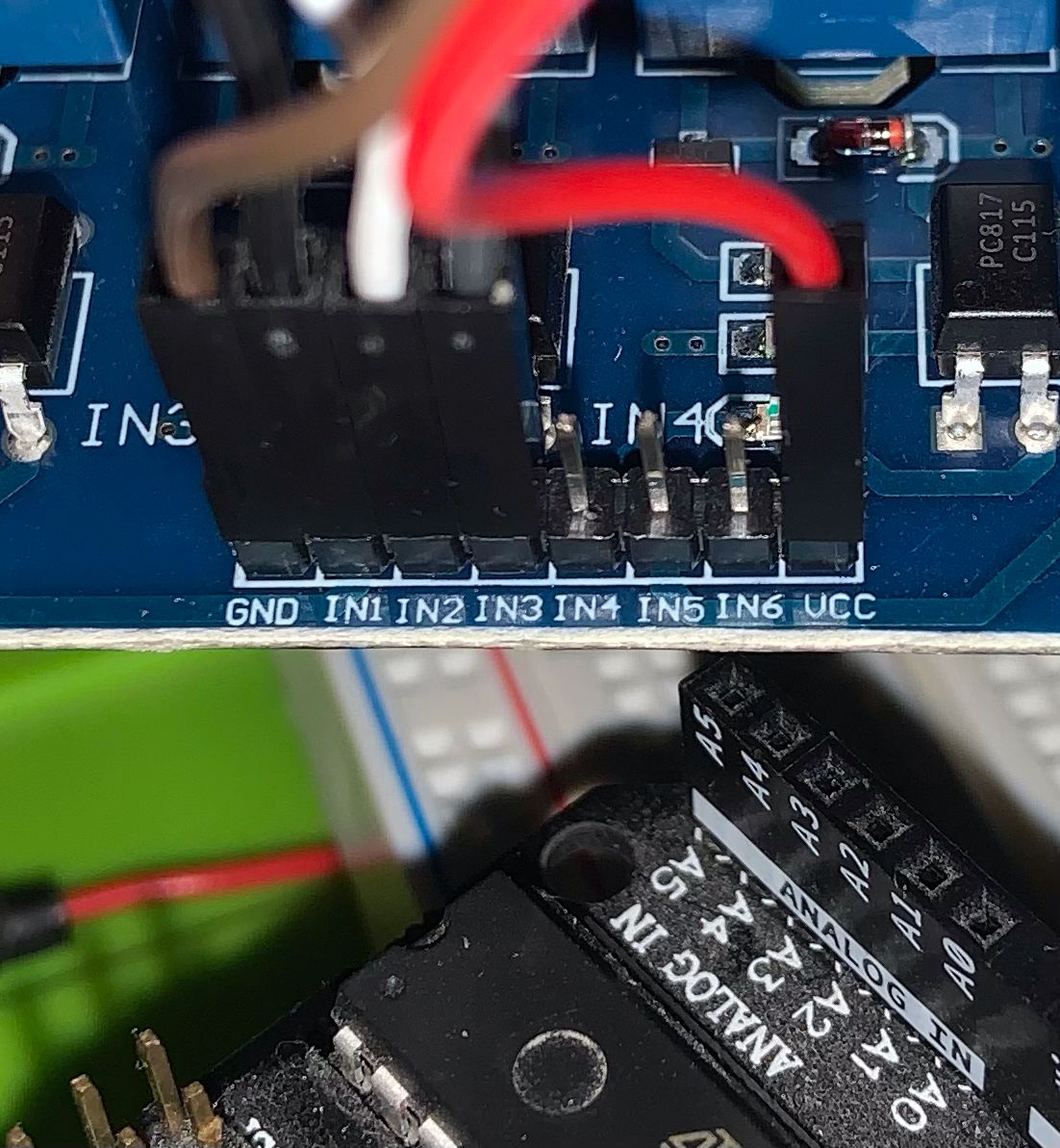
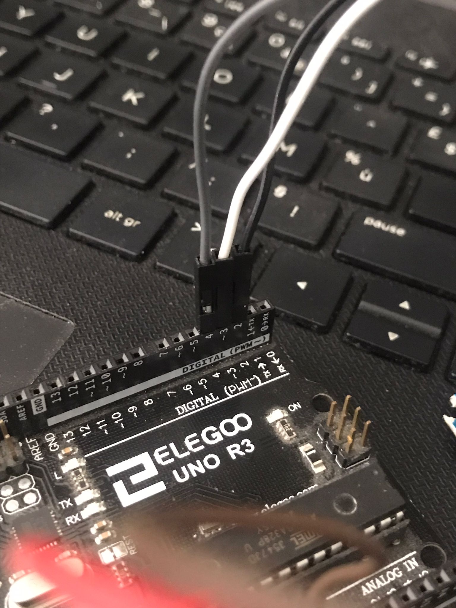
IF you see the closeup photos you ll see the (GND , IN1 , IN2 ....... , VCC) I have connected the GND to the gnd on the arduino and the each INx to a digital input on the arduino and the VCC to the 5V .
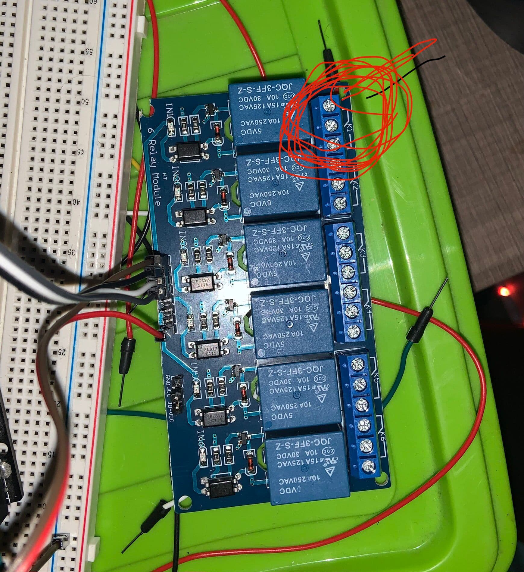
in the second photo I have circulate the part with 3 slots on the relays
Hope that give you a good view to my wiring.
yes
A much clearer set of photos, but nothing shows the wiring up of the relay contacts to the coin. The only ground shown is the ground input to the driver side of the relay board. By the very definition of a relay this is isolated from the contacts. So I still can't see if this bit is wired correctly.
This is important because of the very confusing diagram shown in that video.
Hi,
Please.
Get the pen(cil)s and paper out and post a copy of your circuit a picture of a hand drawn circuit in jpg, png?
Hand drawn and photographed is perfectly acceptable.
Please include ALL hardware, power supplies, component names and pin labels.
Thanks.. Tom.. ![]()
![]()
![]()
![]()
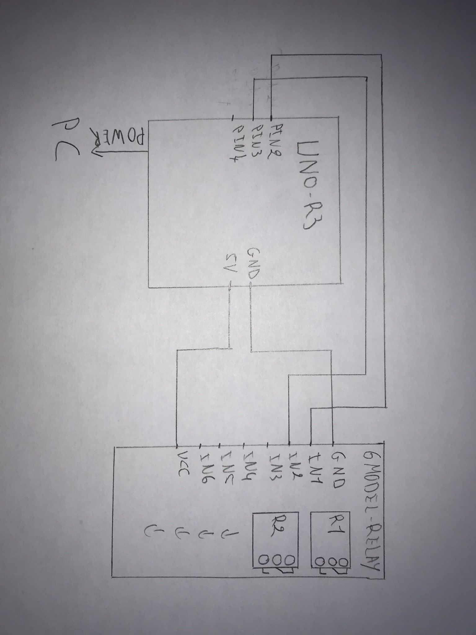

I have tried to draw the circuit by hand . can't upload a pdf fil
here is the 6 model relay I m using : https://fr.aliexpress.com/item/1005005865597217.html?spm=a2g0o.order_list.order_list_main.11.540a5e5bcMtwzg&gatewayAdapt=glo2fra
Hope it give you a better view on my circuit .
But you have failed. Where is the relay contact circuit that you are using to switch the ground onto your coin?
jpg or png is better, everybody can view it in the post.
Good start. ![]()
![]()
Tom.. ![]()
![]()
![]()
![]()
Yes that's the bigger probleme . the relay has 3 output ( the 3 carcel on the relay ) I have tried all of theme and I don't know if its the correct way or you can give me any proposition for how set it up
Thank you.
I did that in post #11
Then I asked you to draw what you had tried, but so far you haven't.