Pretty sure I could tell you soon, as it was my first time today tinkering with one of these HC-SR04 modules. I know that people had been using these for a long time. I only eventually got around to it today.
I have seen code on the internet, where people use delay and PulseIn etc.
I decided to just use port writing commands to generate the 10 microsecond pulse for the trigger - using the old 'if micros() - ref_time > = 10' method ----- even though I understand that our resolution with micros() timing is something like 4 microsecond.
And for the ECHO pulse measurement, I just tied the ECHO pin to two different interrupt pins ... eg. pin 2 and 3 on the UNO, which just allows me to detect rising edge on pin 2, and then the falling edge on pin 3. The time difference between the rising and falling edge is easily handled by these two interrupt pins.
So, to get the delay between the "start" eg. ref_1 of our trigger command pulse (the 10 microsec one) and the "start eg. ref_2" of the ECHO waveform (which I assume to also be the same as the start of the actual ultrasonic transmitted pulse) ...... I assume that the delay would just be "ref_2 - ref_1".
I'm getting a round-trip time (with nothing in front of the sensor) of approx 17000 microsec.
The time difference between the start of the ECHO pulse and the start of the 10 microsec trigger pulse that I'm getting is approx 2272 to 2262 microsecond.
In another thread that I created today, I'm just trying to figure out why sometimes the sensor module is providing a round-trip time of about 70000 microseond.
Thanks Delta_G ..... I'll paste my code. There are some code comments in there. Some assumptions could be wrong, but I only put in the comments to try make sense of what this module actually does. I think I have the right idea, or mostly the right idea about what the ECHO pulse represents - so excuse any possible incorrect commentary in the code.
This code was just used on an UNO, with trigger connected to pin 8, and the ECHO pin connected to BOTH pin 2 and pin 3.
// defines pins numbers
const int trigPin = 8;


const byte interruptPin_2 = 2;   //echo pin number - rising edge trigger
const byte interruptPin_3 = 3;   //echo pin number - falling edge trigger

byte flag = 0;
byte echo_det = 0;

volatile byte state = LOW;


unsigned long ref_tx = 0;
unsigned long ref_rx = 0;
unsigned long duration = 10; //tx pulse duration in microsecond
unsigned long holdoff = 20000;

unsigned long rx_time = 0;

float distance = 300;

float clear_range = 240;
float detect_range = 150;
byte detect = 0;

unsigned long t_det_ref = 0;
unsigned long t_det_duration = 0;

unsigned int count = 0;


void setup() {
  DDRB = B00111111; // set PORTD (digital 8~13) to outputs - 6 pins only. The highest 2 pins are irrelevant.

  attachInterrupt(digitalPinToInterrupt(interruptPin_2), sense_rise, RISING);
  attachInterrupt(digitalPinToInterrupt(interruptPin_3), sense_fall, FALLING);
  Serial.begin(115200); // Starts the serial communication

  PORTB = B00000000;   //pin D8 is the least sig bit.

}


void loop() {
 if (flag == 0) {
  flag = 1;
  PORTB = B00000001;
  ref_tx = micros();
  }

  if ( (flag == 1) && ( micros()-ref_tx >= duration ) ) {    //sends a 10 microsecond pulse to the trigger pin, which gives the actual ultrasonic module the command to send out it's own 8 cycle ultrasonic burst.
    flag = 2;
    //Serial.println("sent pulse");
    PORTB = B00000000;
  }

  if ( (flag == 2) && ( micros() - ref_tx >= holdoff ) ) {     //this is an optional hold-off time so that we can provide some time before we send the next trigger pulse to the ultrasonic module.
    flag = 3;
  }

  if ( (state == HIGH) && (echo_det == 0 )) {                  //this corresponds to the beginning (rising edge) of the 'ECHO' round-trip time-measurement waveform.
    echo_det = 1;
    ref_rx = micros();
  }

    if ( (echo_det == 1) && (state == LOW) ) {            //the important detail to know about the ultrasonic sensor module is that it generates a high going pulse relative to the time it begins to send out its own 8-cycle ultrasonic burst. The pulse remains high until either an echo is received, or after a time-out period occurs. So basically, the duration of this pulse represents the time between start of ultrasonic burst and start of received echo. Halving this time difference, followed by multiplying the halved result by the speed of sound in air (eg. 0.034 cm per microsec) will give distance to the target in units of cm.
    echo_det = 0;
    rx_time = micros() - ref_rx;
    //Serial.print("rx pulse return time microsec = "); Serial.print(rx_time); Serial.print("  "); Serial.print("ref_rx - ref_tx = "); Serial.print(ref_rx - ref_tx); Serial.print("  "); Serial.print("ref_rx_time "); Serial.print(ref_rx); Serial.print("  "); Serial.print("ref_tx "); Serial.println(ref_tx);
    Serial.print("ref_rx - ref_tx = "); Serial.print(ref_rx - ref_tx); Serial.print("  "); Serial.print("ref_rx_time "); Serial.print(ref_rx); Serial.print("  "); Serial.print("ref_tx "); Serial.println(ref_tx);
    distance = rx_time*0.5*0.034;
    //Serial.print("distance cm = "); Serial.println(distance);
        flag = 0;
  }

    if  ( (distance < detect_range ) && (detect == 0) ) {
      detect = 1;
      t_det_ref = micros();
    }

    if ( (detect == 1) && (distance >= clear_range) )  {
      detect = 0;
      t_det_duration = micros() - t_det_ref;
      if (t_det_duration <= 300000) {
        ++count;
        Serial.print("                         valid count");  Serial.print("  ");   Serial.println(count);
      }
    }


}


void sense_rise() {
  state = HIGH;
}

void sense_fall() {
  state = LOW;
}
It shows 450 microseconds from the trigger falling to the rise of the echo signal.
When I wrote some ICP code for an HC SR04 I set the input capture for a rising edge, reset the counters on that edge, and switched the next capture to a falling edge. I did not use rollover, and had the timer tick at .5 us.
volatile unsigned int Ticks;// holds time as .5 us ticks
volatile boolean pulseCaptured = false;

boolean triggerFinished;

const byte trigPin = 7;
const byte echoPin = 8; //icp pin

void setup() {
  //Timer1 Setup
  TCCR1A = 0;   //initialize register
  TCCR1B = 0;  //initialize register
  TCCR1B = (1 << CS11);  // prescaler 8 for .5us tick
  TCCR1B |= (1 << ICES1); //enable input capture edge select rising
  TIMSK1 = _BV(ICIE1);   // enable input capture interrupt for timer 1

  pinMode(trigPin, OUTPUT);
  pinMode(echoPin, INPUT);

  Serial.begin (115200);
  Serial.println("starting...");
}

void loop() {

  if (triggerFinished == false)
  {
    digitalWrite(trigPin, LOW);
    delayMicroseconds(2);
    digitalWrite(trigPin, HIGH);
    delayMicroseconds(10);
    digitalWrite(trigPin, LOW);
    triggerFinished = true;
  }

  if (pulseCaptured == true && triggerFinished == true)
  {
    pulseCaptured = false; //reset
    triggerFinished = false;
    Serial.print(getTick() / 2 / 29.1, 1);
    Serial.print('\t');
    Serial.println("cm");
    delay(1000);
  }
}

ISR(TIMER1_CAPT_vect) {
  if (bitRead(TCCR1B, ICES1)) //bit is set and rising edge selected
  {
    TCNT1 = 0;       // reset the counter
    ICR1 = 0;
    Ticks = 0;
  }
  else {  // falling edge was detected
    Ticks = ICR1;//pulse length
    ICR1 = 0;
    TCNT1 = 0;
    pulseCaptured = true;
  }
  TCCR1B ^= 1 << (ICES1); // toggle bit value to trigger on the other edge
}

unsigned int getTick() {
  unsigned int akaTick = 0;       // holds a copy of the tick count so we can return it after re-enabling interrupts
  cli();             //disable interrupts
  akaTick = Ticks;
  Ticks = 0;
  sei();             // enable interrupts
  return akaTick / 2; //microseconds
}
I find it bizarre that the image at the above link appears to be the only image on the ENTIRE internet that shared this particular timing information.
All other websites that shows trigger and echo diagrams show absolutely NO time-scale details that provide hints about the time duration between start of trig waveform and start of the echo waveform.
At least this site did something, and shared something. And thanks for finding and providing that link!
I was also starting to question my 2270 microsecond value, because 2270 microsecond is much more than 450 microsecond. So I had to take a look for myself as well. I'm measuring approx 2.3 millisecond (2300 microsec). So now I'm wondering if there is a difference between their module and the one I bought (from ebay). My other ultrasonic modules (of the same kind) also provide the same 2.3 millisecond delay between trigger pulse and actual ultrasonic pulse.
The photograph below (taken today) shows 2.5 millisec per division for the time-scale. And, one cursor line is placed at the start of the trigger waveform, while the other is placed at the start of the echo waveform. The 'delta' (difference) information is just out of view ..... but the delta readout says 2.3 millisec. This matches the UNO's readings .... around 2270 microsec.
Also, the figure is showing that I generate a trigger pulse to begin with. An echo waveform then appears and then disappears. And the next trigger pulse is generated immediately after the completion of the ECHO waveform.
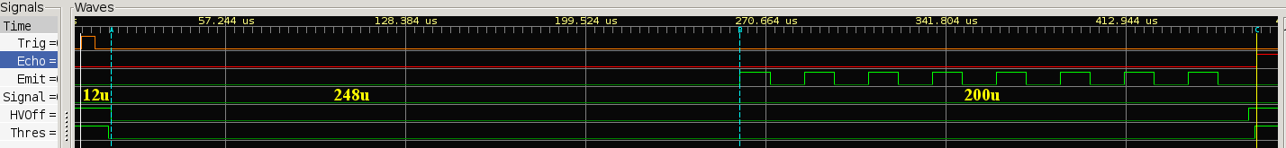
After the trigger input is raised the uP detects it and after some 10us powers on the MAX232. After 248us, time to ramp up the +/-10V of the charge-pump, the 8 pulses 40KHz train is produced and then the power is switched off. During this time the comparator threshold is also kept low to prevent any spurious signals to be detected in the receiver. The circuit then asserts the echo signal and waits for the echo to return. As soon as the first pulse is detected in the receiver the echo signal is deasserted and one can measure the width of the echo pulse to calculate the obstacle distance. There are several problems with this circuit...
And the second claims to achieve sub-millimeter resolution using a phase detection technique.
DaveEvans:
And the second claims to achieve sub-millimeter resolution using a phase detection technique.
Thanks Dave. My measurements with both the UNO and oscilloscope indicate approx. 2300 microsecond for my HC-SR04 modules (for the time between the beginning of the trigger and the beginning of the actual ultrasonic pulse. I measured the same time duration with 2 of the same modules.
If other people can do some measurements too, then we'll be able to see what's happening here with these differences in delays. Cattledog's link indicates 450 microsec. The link you gave claims 250 microsec, etc.
Also.... from this link you gave: the trigger pulse doesn't even look like 10 microsec. Their scale is approx 3.557 microsec per smallest gradation : https://uglyduck.vajn.icu/HC-SR04E/init-echo.png
Also.... at this link here: HC-SR04 | David Pilling ----- they left out time-scale information, which isn't really good at all.
Cattledog's link indicates 450 microsec. The link you gave claims 250 microsec, etc.
I think you are missing the fact of the uglyducklink breaking the timing gap into a 250 microscecond charge pump cycle, and a 200 microsecond ultrasonic pulse train of 8 pulses at 40KHz.
After the trigger input is raised the uP detects it and after some 10us powers on the MAX232. After 248us, time to ramp up the +/-10V of the charge-pump, the 8 pulses 40KHz train is produced and then the power is switched off. During this time the comparator threshold is also kept low to prevent any spurious signals to be detected in the receiver. The circuit then asserts the echo signal and waits for the echo to return. As soon as the first pulse is detected in the receiver the echo signal is deasserted and one can measure the width of the echo pulse to calculate the obstacle distance.
cattledog:
I think you are missing the fact of the uglyducklink breaking the timing gap into a 250 microscecond charge pump cycle, and a 200 microsecond ultrasonic pulse train of 8 pulses at 40KHz.
Thanks cattledog. That makes sense! Will be very interested to see if 450 microsec is the delay for all HC-SR04. I'm interested because I measured 2300 microsec for two modules.
Will be very interested to see if 450 microsec is the delay for all HC-SR04
Lets ask our community. There are enough HC-SR04's out there to collect some data. Here's a simple sketch to run to see the delay time from trigger to echo pulse. If you have an HC-SR04 available, please take a moment to run this sketch and post your results. Inquiring minds want to know.
echoPulseBegin after 452microseconds
echoPulseBegin after 448microseconds
echoPulseBegin after 444microseconds
echoPulseBegin after 448microseconds
echoPulseBegin after 448microseconds
echoPulseBegin after 452microseconds
echoPulseBegin after 448microseconds
cattledog:
Lets ask our community. There are enough HC-SR04's out there to collect some data. Here's a simple sketch to run to see the delay time from trigger to echo pulse. If you have an HC-SR04 available, please take a moment to run this sketch and post your results. Inquiring minds want to know.
Thanks cattledog! I ran your code just a few mins ago.
And I got this : (the other module gets the same result too)
starting...
echoPulseBegin after 2116 microseconds
echoPulseBegin after 2248 microseconds
echoPulseBegin after 2248 microseconds
echoPulseBegin after 2248 microseconds
echoPulseBegin after 2248 microseconds
echoPulseBegin after 2248 microseconds
echoPulseBegin after 2248 microseconds
echoPulseBegin after 2248 microseconds
echoPulseBegin after 2248 microseconds
Also.... thanks to you and your code, I now realise that the trigger event actually begins at the FALLING edge of the trigger 'pulse' ..... instead of the rising edge. Would be interesting to find out why those 'geniuses' designed it like that.
The other thing I can think of right now is ----- whether or not the trigger is merely negative edge-triggered. I will see what happens if I keep the trigger pin at a high voltage for a 'long' time (eg. 5 seconds), followed by taking the trigger pin voltage to a low level.
UPDATE -- from observations using the oscilloscope, 10 microsecond trigger pulses spaced every 3 millisecond will consistently cause an echo waveeform to be generated. But, if the trigger pulses are say 2 millisecond apart (or less), we won't consistently see an echo pulse generated after each and every individual trigger pulse.
Similarly ---- for 'negative edge triggering', which is pretty much what this HC-SR04 module does ....... will work properly if the spacing between each falling edge is say 3 millisecond apart. For example, trigger level is initially high, then abruptly cause a negative edge (then abruptly go high again after say 10 microsecond), then generate the next falling edge 3 millseconds later (then abruptly go high again). If the spacing between the negative edges are too close (such as 2 millisecond spacings or 1 millisecond spacings), then there is no guarantee that an echo waveform come with each negative edge trigger pulse.
Cattledog ....... you'll be surprised (or maybe not surprised) to know that ........ I went out to a local electronic store and decided to (out of curiosity) buy one "seemingly" identical looking module ..... with professional brand packing.
Check out these results ....
starting...
echoPulseBegin after 476 microseconds
echoPulseBegin after 476 microseconds
echoPulseBegin after 476 microseconds
echoPulseBegin after 476 microseconds
echoPulseBegin after 476 microseconds
Upon close inspection ------ there are differences in the board layout.
The nasty thing is ----- the ebay seller that I purchased the 2300 microsecond delay modules from (and I purchased 5 of those) ----- has posted an image of the HC-SR04 module with the same track layout as my newest (purchased today) HC-SR04 module. This means that what they show in their ebay photo is not the same as the module that they send out.
At least these modules are relatively inexpensive. The 470 microsec delay is certainly better than 2300 microsecond delay.
The price I paid for the 'better' single one today costs more than the 5 questionable ones I bought on ebay. Costs more ----- but at least it exhibits the 'usual' performance.
Cattledog ....... you'll be surprised (or maybe not surprised) to know that
In the $1 ebay/china world, nothing would surprise me. My module has the vertical tracks.
EDIT: When looking at Google images for HC-SR04 there are clearly differnt modules, some with horizontal and some with vertical tracks. They appear to have different chip sets of three chips on the back. There is another variation I see with horizontal tracks and only two chips on the back.
That link is certainly of interest to me Dave. Nice one. Now that I have 1 'good' module, I will have to remember to do 1 more test, which is to find out why I'm getting variations in echo waveform width for cases where targets are out of range. For the 'bad' sensors that I had, I was getting 2 different readings, depending on how I held or angled the module (always for the case with targets out of range). I would sometimes get around 16000 microsecond, and other times get about 70000 microsecond, which is sort of ridiculous.
Will be interesting to see what happens with my 'good' sensor that I purchases yesterday. I had forgotten to do the no-target test (ie. echo-pulse time duration measurement for target out-of-range case).
cattledog:
In the $1 ebay/china world, nothing would surprise me. My module has the vertical tracks.
No wonder! You had the good ones! I think what I have to do is to find out which particular ebay sellers have a 'good' chance of selling the 'good' ones. I know that I can't trust photos from the sellers, as those photos don't necessarily align with the actual module they're selling.
For the 'good' sensor module, I observed the duration of the echo waveform on the oscilloscope for the case of target-out-range. This means no objects in the detection range of the module.
Interestingly, for some orientations of the module - with nothing in range (in front of the module), the duration of the echo waveform can alter between two general values ..... ie. approx 16000 and approx 136000...... micro seconds.
These changes in echo waveform duration can readily be seen in oscilloscope measurements.
For the 'bad' sensor module...... similar observations, except the values are generally approx 16000 and approx 70000.
My current opinion of these HC-SR04 modules. Workable for many basic applications. Maybe 1 or 2 basic things that the designer could have improved or fixed before pushing out this product. The first is ----- fix up the glitchy variations in echo waveform duration for the no-target-in-range mode of operation. And the second is ... just design the trigger to be positive edge triggered (or even negative edge triggered).
Delta_G:
Do I understand correctly about the negative triggering?
I was successfully getting negative edge triggers when the trig pin was held high ....... a negative edge (take trig level to 0 volt). Eg. high voltage on the trigger pin, keep it high for as long as we like, then momentarily take the trigger level to 0 volt (for say 10 microsecond, or more) ..... resulted in an echo waveform.
The thing to watch on an oscilloscope is .... the time spacing between triggers. I think it was something like 3 microsecond between triggers guaranteed an echo waveform for every trigger. But spacings of say 1 millisec between triggers would not guarantee an echo waveform being generated for every trigger attempts. I'll have to double-check on this..... but that's what I recall seeing.

