Re-writing clean code (like using arrays and loops instead of repeated lines)

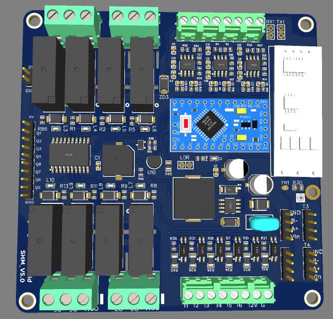
I am working on Rs485 based home automation project. I have attached 02 PCB.

Relay Module : With 06 Input, 08 relay output drive through TPIC6B595DWR and 0-10V output for dimmer.

Wall Panel: 08 Input and 08 output led drive through TPIC6B595DWR.

Nextion HMI : Display / monitor and control all module.

Protocol: Msg based half duplex without feedback. Msg contain (Sender address, Receiver address, function code, status) like 10,100,10,0

Wall panel address 10,11,12,13……

Relay module address 100,101,102,103……

Below sketch is uploaded on Relay module and its working as expected. But I am looking support to arrange and clean the code to write in arrays instead of repeated lines.


#include <RS485_non_blocking.h>

byte My_Address = 100;  //Target_ID
byte Target_ID = 10;    //Target_ID


size_t fWrite(const byte what) {
  return Serial.write(what);
}
int fAvailable() {
  return Serial.available();
}

int fRead() {
  return Serial.read();
}

// RS485 library instance
RS485 myChannel(fRead, fAvailable, fWrite, 20);
byte buf[20];

int count = 10;
int i;

const int Buzzer = 2;
const int latchPin = 7;  //Pin connected to latch pin (RCK) of TPIC6B595
const int clockPin = 4;  //Pin connected to clock pin (SRCK) of TPIC6B595
const int dataPin = 12;  //Pin connected to Data in (SER IN) of TPIC6B595
const int OE = 8;        // clearPin
byte leds;

bool LED_state1 = false;
bool LED_state2 = false;
bool LED_state3 = false;
bool LED_state4 = false;
bool LED_state5 = false;
bool LED_state6 = false;
bool LED_state7 = false;
bool LED_state8 = false;

const int heartBeatLED = 13;
unsigned int heartBeatState = LOW;

bool FeedbackLightState = false;
uint32_t LEDStartTime = 0;

const int Led_Dimmer = 3;  // +- Dimmer
const int Led_CCT = 5;     // +- CCT

const int Led_White = 6;  // CH1 White
const int Led_Blue = 9;   // CH2 Blue

const int Led_Red = 10;    // CH3 Red
const int Led_Green = 11;  // CH4 Green

int Receive_Val1 = 0;
int DIM_write1 = 0;

int Receive_Val2 = 0;
int CCT_write2 = 0;

int Receive_Val3 = 0;
int DIM_write3 = 0;

int Receive_Val4 = 0;
int DIM_write4 = 0;


int Receive_Val5 = 0;
int DIM_write5 = 0;

int Receive_Val6 = 0;
int DIM_write6 = 0;

void setup() {

  Serial.begin(9600);
  myChannel.begin();

  pinMode(OE, OUTPUT);
  digitalWrite(OE, LOW);
  pinMode(latchPin, OUTPUT);
  pinMode(dataPin, OUTPUT);
  pinMode(clockPin, OUTPUT);

  //  checkLedState();

  pinMode(heartBeatLED, OUTPUT);
  digitalWrite(heartBeatLED, LOW);
  pinMode(Buzzer, OUTPUT);
  digitalWrite(Buzzer, LOW);

  pinMode(Led_Dimmer, OUTPUT);
  pinMode(Led_CCT, OUTPUT);
  pinMode(Led_White, OUTPUT);
  pinMode(Led_Blue, OUTPUT);

}  // end of setup
void loop() {

  if (myChannel.update()) {
    memcpy(buf, myChannel.getData(), myChannel.getLength());  // make a copy of the data


    ///////////////////---------Heartbeat-generate-----------/////////////////
    if (buf[0] == 255 && buf[1] == 1 && buf[2] == 94 && buf[3] == 1)  //buf[0] = Slave ID , buf[1] = Button ID ,  buf[2] = Slave ID
    {
      //Serial.println ("Zzzz");
      heartBeatState = HIGH;
      FeedbackLightState = true;
      LEDStartTime = millis();
    }
    /////////////////////////////-------------Door Bell-------------------///////////////////


    if (buf[0] == 20 && buf[1] == 110 && buf[2] == 122 && buf[3] == 1)  //buf[0] = Slave ID , buf[1] = Button ID ,  buf[2] = Slave ID
    {

      while (count > 0) {

        for (i = 0; i < 250; i++) {
          digitalWrite(Buzzer, HIGH);
          delayMicroseconds(i);
          digitalWrite(Buzzer, LOW);
          delayMicroseconds(i);
        }
        delay(100);
        count = count - 1;
      }
      count = 10;
    }
    ///////////////---------------Dimmer-------------------------//////////////////


    ///////////////////////////////////-------------------------------------///////////////////////////
    if (buf[0] != Target_ID)
      return;  // not my device

    if (buf[1] != My_Address)
      return;  // unknown command

    //Serial.println ("Message Received");


    ///////////---------------DIMMER ----------------------------///////////

    /*
 if (buf [2] == 30) {
      Receive_Val1 = buf [3];
      DIM_write1 = map(Receive_Val1, 0, 9, 0, 255);

      //Serial.print ("Serial_Rec : ");
      //Serial.print (Receive_Val1);
      //Serial.print ("    DIM_write1 : ");
      //Serial.println (DIM_write1);
      analogWrite(Led_Dimmer, DIM_write1);

//  byte msg [] = {My_Address , Target_ID, 101, DIM_write1};
//  myChannel.sendMsg (msg, sizeof (msg));
  
      digitalWrite(Buzzer, HIGH);
      FeedbackLightState = true;
      LEDStartTime = millis();
    }


    if (buf [2] == 35) {
      Receive_Val2 = buf [3];
      CCT_write2 = map(Receive_Val2, 0, 9, 0, 255);

      //Serial.print ("Serial_Rec : ");
      //Serial.print (Receive_Val2);
      //Serial.print ("    CCT_write2 : ");
      //Serial.println (CCT_write2);
      analogWrite(Led_CCT, CCT_write2);

 // byte msg [] = {My_Address , Target_ID, 102, CCT_write2};
 // myChannel.sendMsg (msg, sizeof (msg));
  
      digitalWrite(Buzzer, HIGH);
      FeedbackLightState = true;
      LEDStartTime = millis();
    }


        if (buf [2] == 103) {
      Receive_Val3 = buf [3];
      DIM_write3 = map(Receive_Val3, 0, 65, 0, 255);

      //Serial.print ("Serial_Rec : ");
      //Serial.print (Receive_Val3);
      //Serial.print ("    DIM_write3 : ");
      //Serial.println (DIM_write3);
      analogWrite(Led_White, DIM_write3);

      digitalWrite(Buzzer, HIGH);
      FeedbackLightState = true;
      LEDStartTime = millis();
    }


        if (buf [2] == 104) {
      Receive_Val4 = buf [3];
      DIM_write4 = map(Receive_Val4, 0, 65, 0, 255);

      //Serial.print ("Serial_Rec : ");
      //Serial.print (Receive_Val4);
      //Serial.print ("    DIM_write4 : ");
      //Serial.println (DIM_write4);
      analogWrite(Led_Blue, DIM_write4);

      digitalWrite(Buzzer, HIGH);
      FeedbackLightState = true;
      LEDStartTime = millis();
    }


    //////////-------------------------------------------------
     if (buf [2] == 105) {
      Receive_Val5 = buf [3];
      DIM_write5 = map(Receive_Val5, 0, 65, 0, 255);

      //Serial.print ("Serial_Rec : ");
      //Serial.print (Receive_Val5);
      //Serial.print ("    DIM_write5 : ");
      //Serial.println (DIM_write5);
      analogWrite(Led_Red, DIM_write5);

      digitalWrite(Buzzer, HIGH);
      FeedbackLightState = true;
      LEDStartTime = millis();
    }


    if (buf [2] == 106) {
      Receive_Val6 = buf [3];
      DIM_write6 = map(Receive_Val6, 0, 65, 0, 255);

      //Serial.print ("Serial_Rec : ");
      //Serial.print (Receive_Val6);
      //Serial.print ("    DIM_write6 : ");
      //Serial.println (DIM_write6);
      analogWrite(Led_Green, DIM_write6);

      digitalWrite(Buzzer, HIGH);
      FeedbackLightState = true;
      LEDStartTime = millis();
    }

*/
    /////////////////-----------------------------------------------///////////////////////////////////
    //////////////---------------Relay-------------------------///////////////

    if (buf[2] == 10 && buf[3] == 1)  //buf[0] = Slave ID , buf[1] = Button ID ,  buf[2] = Slave ID
    {
      LED_state1 = 1;
      bitSet(leds, 0);
      updateShiftRegister();

      //byte msg[] = { My_Address, Target_ID, 60, 1 };
      //myChannel.sendMsg(msg, sizeof(msg));

      //  EEPROM.update(1, LED_state1);
      //Serial.println(F(" P1 B1 S_ON   "));
      digitalWrite(Buzzer, HIGH);
      FeedbackLightState = true;
      LEDStartTime = millis();
    } else if (buf[2] == 10 && buf[3] == 0) {
      LED_state1 = 0;
      // updateShiftRegister();
      bitClear(leds, 0);
      updateShiftRegister();

      //byte msg[] = { My_Address, Target_ID, 60, 0 };
      //myChannel.sendMsg(msg, sizeof(msg));

      //  EEPROM.update(1, LED_state1);
      //Serial.println(F(" P1 B1 S_OFF  "));
      digitalWrite(Buzzer, HIGH);
      FeedbackLightState = true;
      LEDStartTime = millis();
    }
    /////////////----------------//////////////

    if (buf[2] == 11 && buf[3] == 1)  //buf[0] = Slave ID , buf[1] = Button ID ,  buf[2] = Slave ID
    {
      LED_state2 = 1;

      bitSet(leds, 1);
      updateShiftRegister();

      //byte msg[] = { My_Address, Target_ID, 61, 1 };
      //myChannel.sendMsg(msg, sizeof(msg));

      //  EEPROM.update(2, LED_state2);
      //Serial.println(F(" P1 B2 S_ON   "));
      digitalWrite(Buzzer, HIGH);
      FeedbackLightState = true;
      LEDStartTime = millis();
    } else if (buf[2] == 11 && buf[3] == 0) {
      LED_state2 = 0;

      bitClear(leds, 1);
      updateShiftRegister();

      //byte msg[] = { My_Address, Target_ID, 61, 0 };
      //myChannel.sendMsg(msg, sizeof(msg));
      // EEPROM.update(2, LED_state2);
      //Serial.println(F(" P1 B2 S_OFF  "));
      digitalWrite(Buzzer, HIGH);
      FeedbackLightState = true;
      LEDStartTime = millis();
    }
    /////////////----------------//////////////


    if (buf[2] == 12 && buf[3] == 1)  //buf[0] = Slave ID , buf[1] = Button ID ,  buf[2] = Slave ID
    {
      LED_state3 = 1;
      bitSet(leds, 2);
      updateShiftRegister();
      //byte msg[] = { My_Address, Target_ID, 62, 1 };
      //myChannel.sendMsg(msg, sizeof(msg));
      //  EEPROM.update(3, LED_state3);
      //Serial.println(F(" P1 B3 S_ON   "));
      digitalWrite(Buzzer, HIGH);
      FeedbackLightState = true;
      LEDStartTime = millis();
    } else if (buf[2] == 12 && buf[3] == 0) {
      LED_state3 = 0;

      bitClear(leds, 2);
      updateShiftRegister();

      //byte msg[] = { My_Address, Target_ID, 62, 0 };
      //myChannel.sendMsg(msg, sizeof(msg));

      //  EEPROM.update(3, LED_state3);
      //Serial.println(F(" P1 B3 S_OFF  "));
      digitalWrite(Buzzer, HIGH);
      FeedbackLightState = true;
      LEDStartTime = millis();
    }
    //////////////----------------------------------------///////////////

    if (buf[2] == 13 && buf[3] == 1)  //buf[0] = Slave ID , buf[1] = Button ID ,  buf[2] = Slave ID
    {
      LED_state4 = 1;

      bitSet(leds, 3);
      updateShiftRegister();

      //byte msg[] = { My_Address, Target_ID, 63, 1 };
      //myChannel.sendMsg(msg, sizeof(msg));

      //  EEPROM.update(4, LED_state4);
      //Serial.println(F(" P1 B4 S_ON   "));
      digitalWrite(Buzzer, HIGH);
      FeedbackLightState = true;
      LEDStartTime = millis();
    } else if (buf[2] == 13 && buf[3] == 0) {
      LED_state4 = 0;
      bitClear(leds, 3);
      updateShiftRegister();

      //byte msg[] = { My_Address, Target_ID, 63, 0 };
      //myChannel.sendMsg(msg, sizeof(msg));

      //  EEPROM.update(4, LED_state4);
      //Serial.println(F(" P1 B4 S_OFF  "));
      digitalWrite(Buzzer, HIGH);
      FeedbackLightState = true;
      LEDStartTime = millis();
    }


    //////////////////////////////////////----Panel 02------------/////////////////////////////////////////
    if (buf[2] == 14 && buf[3] == 1)  //buf[0] = Slave ID , buf[1] = Button ID ,  buf[2] = Slave ID
    {
      LED_state5 = 1;
      bitSet(leds, 4);
      updateShiftRegister();

      //byte msg[] = { My_Address, Target_ID, 64, 1 };
      //myChannel.sendMsg(msg, sizeof(msg));

      //  EEPROM.update(5, LED_state5);
      //Serial.println(F(" P1 B5 S_ON   "));
      digitalWrite(Buzzer, HIGH);
      FeedbackLightState = true;
      LEDStartTime = millis();
    } else if (buf[2] == 14 && buf[3] == 0) {
      LED_state5 = 0;

      bitClear(leds, 4);
      updateShiftRegister();

      //byte msg[] = { My_Address, Target_ID, 64, 0 };
      //myChannel.sendMsg(msg, sizeof(msg));

      //  EEPROM.update(5, LED_state5);
      //Serial.println(F(" P1 B5 S_OFF   "));
      digitalWrite(Buzzer, HIGH);
      FeedbackLightState = true;
      LEDStartTime = millis();
    }

    /////////////----------------//////////////

    if (buf[2] == 15 && buf[3] == 1) {
      LED_state6 = 1;

      bitSet(leds, 5);
      updateShiftRegister();

      //byte msg[] = { My_Address, Target_ID, 65, 1 };
      //myChannel.sendMsg(msg, sizeof(msg));

      //  EEPROM.update(6, LED_state6);
      //Serial.println(F(" P1 B6 S_ON   "));
      digitalWrite(Buzzer, HIGH);
      FeedbackLightState = true;
      LEDStartTime = millis();
    } else if (buf[2] == 15 && buf[3] == 0) {
      LED_state6 = 0;
      bitClear(leds, 5);
      updateShiftRegister();

      //byte msg[] = { My_Address, Target_ID, 65, 0 };
      //myChannel.sendMsg(msg, sizeof(msg));

      //  EEPROM.update(6, LED_state6);
      //Serial.println(F(" P1 B6 S_OFF   "));
      digitalWrite(Buzzer, HIGH);
      FeedbackLightState = true;
      LEDStartTime = millis();
    }
    //////////////----------------------------------------///////////////

    if (buf[2] == 16 && buf[3] == 1)  //buf[0] = Slave ID , buf[1] = Button ID ,  buf[2] = Slave ID
    {
      LED_state7 = 1;

      bitSet(leds, 6);
      updateShiftRegister();
      //byte msg[] = { My_Address, Target_ID, 66, 1 };
      //myChannel.sendMsg(msg, sizeof(msg));
      // EEPROM.update(7, LED_state7);
      //Serial.println(F(" P1 B7 S_ON   "));
      digitalWrite(Buzzer, HIGH);
      FeedbackLightState = true;
      LEDStartTime = millis();
    } else if (buf[2] == 16 && buf[3] == 0) {
      LED_state7 = 0;

      bitClear(leds, 6);
      updateShiftRegister();
      //byte msg[] = { My_Address, Target_ID, 66, 0 };
      //myChannel.sendMsg(msg, sizeof(msg));
      //   EEPROM.update(7, LED_state7);
      //Serial.println(F(" P1 B7 S_OFF   "));
      digitalWrite(Buzzer, HIGH);
      FeedbackLightState = true;
      LEDStartTime = millis();
    }

    //////////////----------------------------------------///////////////

    if (buf[2] == 17 && buf[3] == 1)  //buf[0] = Slave ID , buf[1] = Button ID ,  buf[2] = Slave ID
    {
      LED_state8 = 1;

      bitSet(leds, 7);
      updateShiftRegister();
      //byte msg[] = { My_Address, Target_ID, 67, 1 };
      //myChannel.sendMsg(msg, sizeof(msg));
      //   EEPROM.update(8, LED_state8);
      //Serial.println(F(" P1 B8 S_ON   "));
      digitalWrite(Buzzer, HIGH);
      FeedbackLightState = true;
      LEDStartTime = millis();
    } else if (buf[2] == 17 && buf[3] == 0) {
      LED_state8 = 0;

      bitClear(leds, 7);
      updateShiftRegister();
      //byte msg[] = { My_Address, Target_ID, 67, 0 };
      //myChannel.sendMsg(msg, sizeof(msg));
      //  EEPROM.update(8, LED_state8);
      //Serial.println(F(" P1 B8 S_OFF   "));
      digitalWrite(Buzzer, HIGH);
      FeedbackLightState = true;
      LEDStartTime = millis();
    }
    ///////////////////////////////////////////----------Group------------------//////////////////////
    /////////////////////////////////////////////--------------------////////////////////////////////

    //////////////----------------Group------------------------///////////////

    if (buf[2] == 18 && buf[3] == 1)  //buf[0] = Slave ID , buf[1] = Button ID ,  buf[2] = Slave ID
    {

      //byte msg[] = { My_Address, Target_ID, 68, 1 };
      //myChannel.sendMsg(msg, sizeof(msg));
      LED_state1 = 1;
      LED_state2 = 1;
      LED_state3 = 1;
      LED_state4 = 1;

      bitSet(leds, 0);
      updateShiftRegister();
      delay(25);
      bitSet(leds, 1);
      updateShiftRegister();
      delay(25);
      bitSet(leds, 2);
      updateShiftRegister();
      delay(25);
      bitSet(leds, 3);
      updateShiftRegister();

      //   EEPROM.update(8, LED_state8);
      ////Serial.println(F(" P1 B9 S_ON   "));
      digitalWrite(Buzzer, HIGH);
      FeedbackLightState = true;
      LEDStartTime = millis();
    } else if (buf[2] == 18 && buf[3] == 0) {

      //byte msg[] = { My_Address, Target_ID, 68, 0 };
      //myChannel.sendMsg(msg, sizeof(msg));
      LED_state1 = 0;
      LED_state2 = 0;
      LED_state3 = 0;
      LED_state4 = 0;

      //   updateShiftRegister();
      bitClear(leds, 0);
      updateShiftRegister();
      delay(25);
      bitClear(leds, 1);
      updateShiftRegister();
      delay(25);
      bitClear(leds, 2);
      updateShiftRegister();
      delay(25);
      bitClear(leds, 3);
      updateShiftRegister();

      //  EEPROM.update(9, LED_state9);
      ////Serial.println(F(" P1 B9 S_OFF   "));
      digitalWrite(Buzzer, HIGH);
      FeedbackLightState = true;
      LEDStartTime = millis();
    }


    if (buf[2] == 19 && buf[3] == 1)  //buf[0] = Slave ID , buf[1] = Button ID ,  buf[2] = Slave ID
    {

      //byte msg[] = { My_Address, Target_ID, 69, 1 };
      //myChannel.sendMsg(msg, sizeof(msg));

      LED_state5 = 1;
      LED_state6 = 1;
      LED_state7 = 1;
      LED_state8 = 1;

      //    updateShiftRegister();
      bitSet(leds, 4);
      updateShiftRegister();
      delay(25);
      bitSet(leds, 5);
      updateShiftRegister();
      delay(25);
      bitSet(leds, 6);
      updateShiftRegister();
      delay(25);
      bitSet(leds, 7);
      updateShiftRegister();


      digitalWrite(Buzzer, HIGH);
      FeedbackLightState = true;
      LEDStartTime = millis();
    } else if (buf[2] == 19 && buf[3] == 0) {

      //byte msg[] = { My_Address, Target_ID, 69, 0 };
      //myChannel.sendMsg(msg, sizeof(msg));
      LED_state5 = 0;
      LED_state6 = 0;
      LED_state7 = 0;
      LED_state8 = 0;

      //   updateShiftRegister();
      bitClear(leds, 4);
      updateShiftRegister();
      delay(25);
      bitClear(leds, 5);
      updateShiftRegister();
      delay(25);
      bitClear(leds, 6);
      updateShiftRegister();
      delay(25);
      bitClear(leds, 7);
      updateShiftRegister();

      //  EEPROM.update(9, LED_state9);
      ////Serial.println(F(" P1 B9 S_OFF   "));
      digitalWrite(Buzzer, HIGH);
      FeedbackLightState = true;
      LEDStartTime = millis();
    }


    /////////////////////-------All At Panel 01----------------////////////////

    if (buf[2] == 20 && buf[3] == 1)  //buf[0] = Slave ID , buf[1] = Button ID ,  buf[2] = Slave ID
    {

      //byte msg[] = { My_Address, Target_ID, 70, 1 };
      //myChannel.sendMsg(msg, sizeof(msg));

      LED_state1 = 1;
      LED_state2 = 1;
      LED_state3 = 1;
      LED_state4 = 1;
      LED_state5 = 1;
      LED_state6 = 1;
      LED_state7 = 1;
      LED_state8 = 1;

      //    updateShiftRegister();
      bitSet(leds, 0);
      updateShiftRegister();
      delay(25);
      bitSet(leds, 1);
      updateShiftRegister();
      delay(25);
      bitSet(leds, 2);
      updateShiftRegister();
      delay(25);
      bitSet(leds, 3);
      updateShiftRegister();
      delay(25);
      bitSet(leds, 4);
      updateShiftRegister();
      delay(25);
      bitSet(leds, 5);
      updateShiftRegister();
      delay(25);
      bitSet(leds, 6);
      updateShiftRegister();
      delay(25);
      bitSet(leds, 7);
      updateShiftRegister();


      digitalWrite(Buzzer, HIGH);
      FeedbackLightState = true;
      LEDStartTime = millis();
    } else if (buf[2] == 20 && buf[3] == 0) {

      //byte msg[] = { My_Address, Target_ID, 70, 0 };
      //myChannel.sendMsg(msg, sizeof(msg));

      LED_state1 = 0;
      LED_state2 = 0;
      LED_state3 = 0;
      LED_state4 = 0;
      LED_state5 = 0;
      LED_state6 = 0;
      LED_state7 = 0;
      LED_state8 = 0;

      bitClear(leds, 0);
      updateShiftRegister();
      delay(25);
      bitClear(leds, 1);
      updateShiftRegister();
      delay(25);
      bitClear(leds, 2);
      updateShiftRegister();
      delay(25);
      bitClear(leds, 3);
      updateShiftRegister();
      delay(25);
      bitClear(leds, 4);
      updateShiftRegister();
      delay(25);
      bitClear(leds, 5);
      updateShiftRegister();
      delay(25);
      bitClear(leds, 6);
      updateShiftRegister();
      delay(25);
      bitClear(leds, 7);
      updateShiftRegister();

      //  EEPROM.update(9, LED_state9);
      ////Serial.println(F(" P1 B9 S_OFF   "));
      digitalWrite(Buzzer, HIGH);
      FeedbackLightState = true;
      LEDStartTime = millis();
    }


    ///////////////////////////////////////////////----------------------------------/////////////


    ///////////------Feedback-------------////////////////////
    /*
      byte msg [] = {2, 1, 1,0};
      myChannel.sendMsg (msg, sizeof (msg));


    */

    ///////////-----------Feedback-------------////////////////////

  }  //END Channel UPDATE

  ////////////////////////////////----------------------/////////////

  if (FeedbackLightState == true && millis() - LEDStartTime >= 50) {
    digitalWrite(Buzzer, LOW);
    heartBeatState = LOW;
    FeedbackLightState = false;
  }
  digitalWrite(heartBeatLED, heartBeatState);
  /////////////////////////---------------------------///////////////////////


}  // end of loop


void updateShiftRegister() {
  digitalWrite(latchPin, LOW);
  shiftOut(dataPin, clockPin, LSBFIRST, leds);
  digitalWrite(latchPin, HIGH);
}

Start bt stepping away from the code and writing out a table.

Your repeated code is different in some ways, and exzctly the same structurally.

I think some two characters control some outputs. I'm in transit so cannot use my usual tools.

So make a simple chart or table, no code

A and B  turn on output 6
C and D turn on output 3

Obvsly using your requirements.

There's low lying fruit, too, like repeated instances of

      digitalWrite(Buzzer, HIGH);
      FeedbackLightState = true;
      LEDStartTime = millis();

That might be a function

void nameThisBetter() {
      digitalWrite(Buzzer, HIGH);
      FeedbackLightState = true;
      LEDStartTime = millis();
}

and eveywhere you need to, just call it

  nameThisBetter();

Have you used functions? Are you comfortable with arrays? These are the key language features you need to be up to speed on, and they form the basis for writing code that is generalized so a function can handle every variation of the same thing that is now your repeated code.

a7

1 Like

Looking at the code, one can see eight copies of a relay handler. This is taken from the middle of your sketch:

// ----- Relay Block 5 -----
int command5  = digitalRead(commandPin5);
int sense5    = digitalRead(sensePin5);

if (command5 != lastCommand5) {
   lastCommand5 = command5;
   if (command5 == HIGH) {
       digitalWrite(relay5Pin, HIGH);
       relay5State = HIGH;
   } else {
       digitalWrite(relay5Pin, LOW);
       relay5State = LOW;
   }
   lastChange5 = millis();
}

if (sense5 != relay5State) {
   // fault detection, retry, error LED, etc...
}

It’s clear your code grew by copy/paste/editing. Here’s a generic version of that same block, with the variable names "anonymized". Nothing about the logic changes - only the names are made generic - and you can see it’s an exact match for all eight relay handlers:

// ----- Relay Block (generic shape) -----
int anyCommand  = digitalRead(anyCommandPin);
int anySense    = digitalRead(anySensePin);

if (anyCommand != anyLastCommand) {
   anyLastCommand = anyCommand;
   if (anyCommand == HIGH) {
       digitalWrite(anyRelayPin, HIGH);
       anyRelayState = HIGH;
   } else {
       digitalWrite(anyRelayPin, LOW);
       anyRelayState = LOW;
   }
   anyLastChange = millis();
}

if (anySense != anyRelayState) {
   // fault detection, retry, error LED, etc...
}

When code is grown by copy/paste/editing, the right tool for compactness and clarity is a function. And when variables are created just by appending numbers or letters - for example, names like relay1Pin, relay2Pin, relay3Pin &c., it's a sign we can replace all of those individual variables with one array.

Arrays allow us to give one name to a whole family of related values, and we select the member we want using an index. For a good introduction to arrays, see the Arduino documentation page on that topic.

https://docs.arduino.cc/language-reference/en/variables/data-types/array/

Here’s what the relay-handling code looks like when rewritten to assume the supporting variables have been placed into arrays. This version becomes a function, which is the final key to compact code and makes it possible to use simple loops instead of eight separate blocks:

Assume we have arrays like:

int commandPin[8];
int sensePin[8];
int relayPin[8];

int lastCommand[8];
int relayState[8];
unsigned long lastChange[8];

we can write a function

void handleRelayCommand(int idx)
{
   int command  = digitalRead(commandPin[idx]);
   int sensed   = digitalRead(sensePin[idx]);

   // Detect command change
   if (command != lastCommand[idx]) {
       lastCommand[idx] = command;

       if (command == HIGH) {
           digitalWrite(relayPin[idx], HIGH);
           relayState[idx] = HIGH;
       } else {
           digitalWrite(relayPin[idx], LOW);
           relayState[idx] = LOW;
       }

       lastChange[idx] = millis();
   }

   // Optional: verify relay output matches expected state
   if (sensed != relayState[idx]) {
       // fault detection or corrective action
   }
}

and call it with one number, idx, which tells it which of the 8 code blocks (numbered 0, 1, 2 .. 7) it should be concerned with.

For more on how functions work and how to define them, see the Arduino reference page on functions:

https://docs.arduino.cc/learn/programming/functions/

The resulting code is shorter, which makes it easier to read, understand, fix and enhance. Instead of carefully editing eight nearly identical code blocks, any improvement to this one function benefits every relay automatically.

I could not test this function, but this illustrates the potential. There is another entire group of copy/paste/edited sections concerning themselves with some kind of dimmer. These six repeated code blocks can be collapsed in identical fashion into one function that uses arrays and indexing to customize its operations

I spoke of low fruit; there are 27 identical "feedback/buzzer" blocks, so as I suggested first above, there's an easy function to write and back fit, which will shorten your sketch by one hundred lines or so.

I did not have to look at what your project is all about; it may be that a different approach to improving this would pop out if I had done. This is all strictly pattern recognition and knowing how to use arrays and functions. I offer it as an example of what you could do here.

a7

What about:

#include <RS485_non_blocking.h>

// ---------------------------------------------------
// RS485
// ---------------------------------------------------
byte My_Address = 100;
byte Target_ID  = 10;

size_t fWrite(const byte what) { return Serial.write(what); }
int    fAvailable()            { return Serial.available(); }
int    fRead()                 { return Serial.read(); }

RS485 myChannel(fRead, fAvailable, fWrite, 20);
byte buf[20];

// ---------------------------------------------------
// Hardware Pins
// ---------------------------------------------------
const int Buzzer    = 2;
const int latchPin  = 7;
const int clockPin  = 4;
const int dataPin   = 12;
const int OE        = 8;
const int heartBeatLED = 13;

byte leds = 0;

// ---------------------------------------------------
// LED state array (8 relays)
// ---------------------------------------------------
bool LED_state[8] = {0};

// ---------------------------------------------------
bool FeedbackLightState = false;
uint32_t LEDStartTime   = 0;
unsigned int heartBeatState = LOW;

// ---------------------------------------------------
// Setup
// ---------------------------------------------------
void setup() {
  Serial.begin(9600);
  myChannel.begin();

  pinMode(OE, OUTPUT);   digitalWrite(OE, LOW);
  pinMode(latchPin, OUTPUT);
  pinMode(clockPin, OUTPUT);
  pinMode(dataPin, OUTPUT);

  pinMode(heartBeatLED, OUTPUT);
  pinMode(Buzzer, OUTPUT);
  digitalWrite(Buzzer, LOW);
  digitalWrite(heartBeatLED, LOW);
}

// ---------------------------------------------------
// Utils
// ---------------------------------------------------
void updateShiftRegister() {
  digitalWrite(latchPin, LOW);
  shiftOut(dataPin, clockPin, LSBFIRST, leds);
  digitalWrite(latchPin, HIGH);
}

void beepFeedback() {
  digitalWrite(Buzzer, HIGH);
  FeedbackLightState = true;
  LEDStartTime = millis();
}

void setRelay(byte index, bool state) {
  LED_state[index] = state;

  if (state) bitSet(leds, index);
  else       bitClear(leds, index);

  updateShiftRegister();
  beepFeedback();
}

void setRelayGroup(byte start, byte end, bool state) {
  for (byte i = start; i <= end; i++) {
    setRelay(i, state);
    delay(25);  // preserve your visual sequence effect
  }
}

// ---------------------------------------------------
// Heartbeat
// ---------------------------------------------------
void processHeartbeat() {
  heartBeatState = HIGH;
  beepFeedback();
}

// ---------------------------------------------------
// Doorbell
// ---------------------------------------------------
void processDoorBell() {
  for (int k = 0; k < 10; k++) {
    for (int i = 0; i < 250; i++) {
      digitalWrite(Buzzer, HIGH); delayMicroseconds(i);
      digitalWrite(Buzzer, LOW);  delayMicroseconds(i);
    }
    delay(100);
  }
}

// ---------------------------------------------------
// ---------------------------------------------------
// Process Relay Single Channels (10–17)
// ---------------------------------------------------
void processRelayCommand(byte cmd, byte val) {
  if (cmd < 10 || cmd > 17) return;

  byte index = cmd - 10;   // relay index 0–7
  setRelay(index, val == 1);
}

// ---------------------------------------------------
// Process Group Commands (18–20)
// ---------------------------------------------------
void processGroupCommand(byte cmd, byte val) {
  bool state = (val == 1);

  switch (cmd) {
    case 18: setRelayGroup(0, 3, state); break;
    case 19: setRelayGroup(4, 7, state); break;
    case 20: setRelayGroup(0, 7, state); break;
  }
}

// ---------------------------------------------------
// Main Loop
// ---------------------------------------------------
void loop() {

  if (myChannel.update()) {
    memcpy(buf, myChannel.getData(), myChannel.getLength());

    // ------------------ Heartbeat -------------------
    if (buf[0] == 255 && buf[1] == 1 && buf[2] == 94 && buf[3] == 1)
      processHeartbeat();

    // ------------------ Doorbell ---------------------
    if (buf[0] == 20 && buf[1] == 110 && buf[2] == 122 && buf[3] == 1)
      processDoorBell();

    // ------------------ Device Filters ---------------
    if (buf[0] != Target_ID) return;
    if (buf[1] != My_Address) return;

    byte command = buf[2];
    byte value   = buf[3];

    // ------------------ Single Relays (10–17) --------
    if (command >= 10 && command <= 17)
      processRelayCommand(command, value);

    // ------------------ Groups (18–20) ---------------
    else if (command >= 18 && command <= 20)
      processGroupCommand(command, value);

  } // end myChannel.update()

  // Turn off buzzer + heartbeat after timeout
  if (FeedbackLightState && millis() - LEDStartTime >= 50) {
    digitalWrite(Buzzer, LOW);
    heartBeatState = LOW;
    FeedbackLightState = false;
  }

  digitalWrite(heartBeatLED, heartBeatState);
}

I didn't do it myself, I asked the AI "Can you do code factorization on this for my Arduino:"...
(EDIT: I didn't check it either...)

Yeah, or do that.

a7

"what" does it do for you? not "how" is does it". in detail

in a way that someone without any programming skill can understand

separate the "dumb" ability to send/recieve msgs and to control the outputs or read the sensors of a node from the "intelligence" that knows "what" to do by monitoring sensors and determining the states of the outputs.

this is similar to monitoring and controlling a large model RR via rs-485

what is the msg format?

couldn'd a generic msg specified an address and one or more bytes corresponding to the state of 8 or more outputs without needing to know what the outputs drive? and if there different types of outputs, a msg parameter specified the type of processing required for msg to handle odd case such as a "dimmer"

And can't the node respond with the state of all it's inputs after receiving a message matching it's address

I am using Nick gammon non blocking library to send the msg.

when push the button from wall panel or Nextion display it will send the msg on bus as below

 byte msg[] = { 10, 100, 10, 1 };  
 myChannel.sendMsg(msg, sizeof(msg));

I have 05 wall panel with address 10,11,12,13,14

05 Relay module with address 100,101,102,103,104

08 Button with address 10,11,12,13,14,15,16,17,18 19 and 20 Group of relay On/OFF

Last byte state 1=On, 0= OFF.

Relay modue will receive this msg and compare the address. Once address match than shift regester will drive related relay only.


    if (buf[0] != Target_ID)
      return;  // not my device

    if (buf[1] != My_Address)
      return;  // unknown command
 if (buf[2] == 10 && buf[3] == 1)  //buf[0] = Slave ID , buf[1] = Button ID ,  buf[2] = Slave ID
    {
      LED_state1 = 1;
      bitSet(leds, 0);
      updateShiftRegister();

      //byte msg[] = { My_Address, Target_ID, 10, 1 }; // For feedback only
      //myChannel.sendMsg(msg, sizeof(msg));

      //  EEPROM.update(1, LED_state1);
      //Serial.println(F(" P1 B1 S_ON   "));
      digitalWrite(Buzzer, HIGH);
      FeedbackLightState = true;
      LEDStartTime = millis();
    } else if (buf[2] == 10 && buf[3] == 0) {
      LED_state1 = 0;
      // updateShiftRegister();
      bitClear(leds, 0);
      updateShiftRegister();

      //byte msg[] = { My_Address, Target_ID, 10, 0 };
      //myChannel.sendMsg(msg, sizeof(msg));

      //  EEPROM.update(1, LED_state1);
      //Serial.println(F(" P1 B1 S_OFF  "));
      digitalWrite(Buzzer, HIGH);
      FeedbackLightState = true;
      LEDStartTime = millis();
    }

Same way push button from wall panel generate the msg which will increased / decresed the dimmer light.

what is the format of the msg? what do each byte in the msg mean?

Thanks for your good time and comment. I am not good in programing, tring to learn somethink new for me. Hopefully I will gain some knowlage from your support. I will try to understand your comment.

1st byte is sender address , like 10,11,12,13,14

2nd byte receiver address, like 100,101,102,103,104

3rd byte Switch number, like 10,11,12,13,14,15,16,17,18 If >=50 mean ts dimmer

4th byte command to change state.

Dimmer case : 3rd byte >=50 is dimmer and 4th byte hold the value level between 0-10

does each node have these same "switches"? if so, why not 0-7?

toggle - if on, turn off, if off, turn off. if so, what happens if a msg is lost and the controller loses track of the current state.

why not one byte where each bit indiates the desired state of the switch?

Original code 750 lines

AI code 170 lines.

I throw my hat into the ring (compiles, did not try to run/test) 160 lines...

Compiled on Nano R3...

Sketch uses 3998 bytes (13%) of program storage space. Maximum is 30720 bytes.
Global variables use 250 bytes (12%) of dynamic memory, leaving 1798 bytes for local variables. Maximum is 2048 bytes.

Original re-writen... I added two functions (at the end) to reduce redundancy... more could be reduced.

#include <RS485_non_blocking.h>
byte My_Address = 100;  //Target_ID
byte Target_ID = 10;    //Target_ID

size_t fWrite(const byte what) {
  return Serial.write(what);
}

int fAvailable() {
  return Serial.available();
}

int fRead() {
  return Serial.read();
}

// RS485 library instance
RS485 myChannel(fRead, fAvailable, fWrite, 20);
byte buf[20];
int count = 10;
int i;

byte leds;
bool LED_state[] = { false, false, false, false, false, false, false, false};
const int heartBeatLED = 13;
unsigned int heartBeatState = LOW;
bool FeedbackLightState = false;
uint32_t LEDStartTime = 0;

const int Buzzer = 2;
const int latchPin = 7;  //Pin connected to latch pin (RCK) of TPIC6B595
const int clockPin = 4;  //Pin connected to clock pin (SRCK) of TPIC6B595
const int dataPin = 12;  //Pin connected to Data in (SER IN) of TPIC6B595
const int OE = 8;        // clearPin

const int Led_Dimmer = 3;  // +- Dimmer
const int Led_CCT = 5;     // +- CCT
const int Led_White = 6;  // CH1 White
const int Led_Blue = 9;   // CH2 Blue
const int Led_Red = 10;    // CH3 Red
const int Led_Green = 11;  // CH4 Green

int Receive_Val[] = {0, 0, 0, 0, 0, 0};

void setup() {
  Serial.begin(115200);
  myChannel.begin();
  for (int i = 2; i < 14; i++)
    pinMode(i, OUTPUT);
  digitalWrite(Buzzer, LOW);
  digitalWrite(OE, LOW);
  digitalWrite(heartBeatLED, LOW);
}  // end of setup

void loop() {
  if (myChannel.update()) {
    memcpy(buf, myChannel.getData(), myChannel.getLength());  // make a copy of the data

    ///////////////////---------Heartbeat-generate-----------/////////////////
    if (buf[0] == 255 && buf[1] == 1 && buf[2] == 94 && buf[3] == 1)  //buf[0] = Slave ID , buf[1] = Button ID ,  buf[2] = Slave ID
    {
      //Serial.println ("Zzzz");
      heartBeatState = HIGH;
      FeedbackLightState = true;
      LEDStartTime = millis();
    }

    /////////////////////////////-------------Door Bell-------------------///////////////////
    if (buf[0] == 20 && buf[1] == 110 && buf[2] == 122 && buf[3] == 1)  //buf[0] = Slave ID , buf[1] = Button ID ,  buf[2] = Slave ID
    {
      while (count > 0) {
        for (i = 0; i < 250; i++) {
          digitalWrite(Buzzer, HIGH);
          delayMicroseconds(i);
          digitalWrite(Buzzer, LOW);
          delayMicroseconds(i);
        }
        delay(100);
        count = count - 1;
      }
      count = 10;
    }

    ///////////////---------------Dimmer-------------------------//////////////////
    if (buf[0] != Target_ID)
      return;  // not my device
    if (buf[1] != My_Address)
      return;  // unknown command

    //////////////---------------Relay-------------------------///////////////
    for (int i = 0; i < 4; i++) {
      if (buf[2] == i + 10 && buf[3] == 1) //buf[0] = Slave ID , buf[1] = Button ID ,  buf[2] = Slave ID
      {
        updateLEDs(i, i + 1, 1);
      } else if (buf[2] == i + 10 && buf[3] == 0) {
        updateLEDs(i, i + 1, 0);
      }
    }

    //////////////////////////////////////----Panel 02------------/////////////////////////////////////////
    for (int i = 4; i < 8; i++) {
      if (buf[2] == 10 + i && buf[3] == 1)
      {
        updateLEDs(i, i + 1, 1);
      } else if (buf[2] == 10 + i && buf[3] == 0) {
        updateLEDs(i, i + 1, 0);
      }
    }

    //////////////----------------Group------------------------///////////////
    if (buf[2] == 18 && buf[3] == 1)  //buf[0] = Slave ID , buf[1] = Button ID ,  buf[2] = Slave ID
    {
      updateLEDs(0, 4, 1);
    } else if (buf[2] == 18 && buf[3] == 0) {
      updateLEDs(0, 4, 0);
    }

    if (buf[2] == 19 && buf[3] == 1)  //buf[0] = Slave ID , buf[1] = Button ID ,  buf[2] = Slave ID
    {
      updateLEDs(0, 8, 1);
    } else if (buf[2] == 19 && buf[3] == 0) {
      updateLEDs(4, 8, 0);
    }

    /////////////////////-------All At Panel 01----------------////////////////
    if (buf[2] == 20 && buf[3] == 1)  //buf[0] = Slave ID , buf[1] = Button ID ,  buf[2] = Slave ID
    {
      updateLEDs(0, 8, 1);
    } else if (buf[2] == 20 && buf[3] == 0) {
      updateLEDs(0, 8, 0);
    }
  }  //END Channel UPDATE

  ///////////-----------Feedback-------------////////////////////
  if (FeedbackLightState == true && millis() - LEDStartTime >= 50) {
    digitalWrite(Buzzer, LOW);
    heartBeatState = LOW;
    FeedbackLightState = false;
  }
  digitalWrite(heartBeatLED, heartBeatState);
}  // end of loop

void updateShiftRegister() {
  digitalWrite(latchPin, LOW);
  shiftOut(dataPin, clockPin, LSBFIRST, leds);
  digitalWrite(latchPin, HIGH);
}

void updateLEDs(int first, int last, int state) {
  for (int i = first; i < last; i++) {
    LED_state[i] = state;
    bitClear(leds, i);
    updateShiftRegister();
    delay(25);
  }
  buzzLightState();
  LEDStartTime = millis();
}

void buzzLightState() {
  digitalWrite(Buzzer, HIGH);
  FeedbackLightState = true;
}

This is a long way to go to turn on and off the LED:

      if (buf[2] == 10 + i && buf[3] == 1)
      {
        updateLEDs(i, i + 1, 1);
      } else if (buf[2] == 10 + i && buf[3] == 0) {
        updateLEDs(i, i + 1, 0);
      }

AI.

a7

here's how a single byte of data can update 8 outputs (bear in mind i'm testing this with ascii value entered from a keyboard. They are none the less valid bytes of data)

const byte PinOut [] = { 13, 12, 11, 10, 9, 8, 7, 6 };
const int  NpinOut    = sizeof(PinOut);

char s [90];

const byte MyAddr = 'g';

// -----------------------------------------------------------------------------
void
updateOutput (
    char buf )
{
    sprintf (s, "updateOutput: 0x%02x", buf);
    Serial.println (s);

    for (int n = 0; n < NpinOut; n++)  {
        digitalWrite (PinOut [n], buf & 1);
        buf >>= 1;
    }
}

// -----------------------------------------------------------------------------
void loop ()
{
    if (Serial.available ())  {
        byte buf [90];
        int n = Serial.readBytesUntil ('\n', buf, sizeof(buf)-1);

        if (2 <= n)  {
            if (MyAddr == buf [0])
                updateOutput (buf [1]);
            else  {
                sprintf (s, "loop: not my addr 0x%02x", buf [0]);
                Serial.println (s);
            }
        }
    }
}

// -----------------------------------------------------------------------------
void setup ()
{
    Serial.begin (9600);

    for (int n = 0; n < NpinOut; n++)  {
        pinMode (PinOut [n], OUTPUT);
    }
}

a similar approach can be used to read a set of inputs into a single byte and send that value along with src and destination addresses whenever a msg corresponding to MyAddr is received

Instead of just asking AI to rewrite the sketch, I asked it to write a skeleton sketch. After I asked it to tell me what the sketch does.

Since most of the work is done in repeated code sections, and the rest of the logic is just parsing the command, I told the AI to make the connection between commands and actions explicit, focusing on the command decoding.

I am not surprised that my peephole work was premature. I did say knowing what this sketch is trying to accomplish might mean doing things differently.

Here's what it wrote:

//----------------------------------------------------
// RS485 COMMUNICATION SETUP (matches original)
//----------------------------------------------------

// Original used: sender → receiver → command → value
// This block only prepares the channel and I/O functions.

void setupCommunication() {
 // Serial + RS485 shim (same as original)
 Serial.begin(9600);
 myChannel.begin();
}

// Reads incoming RS485 packets when available.
bool readPacket() {
 return myChannel.update();
}

// Fetch packet bytes into buf[] exactly like the original did.
void fetchPacketBytes() {
 memcpy(buf, myChannel.getData(), myChannel.getLength());
}


//----------------------------------------------------
// PACKET INTERPRETATION RULES (from user’s description)
//----------------------------------------------------
//
//  buf[0] = sender ID
//  buf[1] = my device ID
//  buf[2] = command number:
//       10–17 → single relays (0–7)
//       18–20 → group operations
//       >= 50 → dimmer channels
//
//  buf[3] = value (0/1 for relay, 0–10 for dimmer)
//
//----------------------------------------------------

bool packetIsForMe() {
 return buf[1] == My_Address;
}

bool isHeartbeatPacket() {
 return (buf[0] == 255 && buf[1] == 1 && buf[2] == 94 && buf[3] == 1);
}

bool isDoorbellPacket() {
 return (buf[0] == 20 && buf[1] == 110 && buf[2] == 122 && buf[3] == 1);
}


//----------------------------------------------------
// OUTPUT HARDWARE SETUP (shift register, LED, buzzer)
// matches original setup()
//----------------------------------------------------

void setupOutputs() {
 pinMode(OE, OUTPUT);        digitalWrite(OE, LOW);
 pinMode(latchPin, OUTPUT);
 pinMode(clockPin, OUTPUT);
 pinMode(dataPin, OUTPUT);

 pinMode(heartBeatLED, OUTPUT);
 pinMode(Buzzer, OUTPUT);

 digitalWrite(Buzzer, LOW);
 digitalWrite(heartBeatLED, LOW);
}


//----------------------------------------------------
// SHIFT REGISTER UPDATE (unchanged behavior)
//----------------------------------------------------
void updateShiftRegister() {
 digitalWrite(latchPin, LOW);
 shiftOut(dataPin, clockPin, LSBFIRST, leds);
 digitalWrite(latchPin, HIGH);
}


//----------------------------------------------------
// FEEDBACK BEEP (same 50 ms buzzer pulse)
//----------------------------------------------------
void startFeedbackBeep() {
 digitalWrite(Buzzer, HIGH);
 FeedbackLightState = true;
 LEDStartTime = millis();
}

void processFeedbackTimeout() {
 if (FeedbackLightState && millis() - LEDStartTime >= 50) {
   digitalWrite(Buzzer, LOW);
   heartBeatState = LOW;
   FeedbackLightState = false;
 }
}


//----------------------------------------------------
// RELAY CONTROL (single channels 10–17)
//----------------------------------------------------
void setRelay(byte index, bool state) {
 LED_state[index] = state;

 if (state) bitSet(leds, index);
 else       bitClear(leds, index);

 updateShiftRegister();
 startFeedbackBeep();
}


//----------------------------------------------------
// GROUP CONTROL (18, 19, 20) — same effects as original
//----------------------------------------------------
void setRelayGroup(byte start, byte end, bool state) {
 for (byte i = start; i <= end; i++) {
   setRelay(i, state);
   delay(25);   // preserves original visual effect
 }
}


//----------------------------------------------------
// DIMMER HANDLING (newly clarified from user description)
//----------------------------------------------------
bool commandIsDimmer(byte cmd) {
 return cmd >= 50;   // exactly as described by inquirer
}

void processDimmerCommand(byte cmd, byte level) {
 // original sketch had *no* dimmer logic,
 // but the protocol spec guarantees this will be needed.
 //
 // Placeholder for future implementation.
 // You may map cmd→channel using a table here.
}


//----------------------------------------------------
// COMMAND DISPATCH (core of the original sketch)
//----------------------------------------------------
void handleCommand() {

 byte command = buf[2];
 byte value   = buf[3];

 if (command >= 10 && command <= 17) {
   // → relay index 0–7
   setRelay(command - 10, value == 1);
 }

 else if (command >= 18 && command <= 20) {
   bool state = (value == 1);

   switch (command) {
     case 18: setRelayGroup(0, 3, state); break;
     case 19: setRelayGroup(4, 7, state); break;
     case 20: setRelayGroup(0, 7, state); break;
   }
 }

 else if (commandIsDimmer(command)) {
   processDimmerCommand(command, value);
 }
}


//----------------------------------------------------
// MAIN LOOP — exactly follows the original logic
//----------------------------------------------------
void loop() {

 // ------------------- Read communication -------------------
 if (readPacket()) {
   fetchPacketBytes();

   // Heartbeat (unchanged)
   if (isHeartbeatPacket()) {
     heartBeatState = HIGH;
     startFeedbackBeep();
   }

   // Doorbell (unchanged)
   if (isDoorbellPacket()) {
     processDoorBell();
   }

   // Ignore packets not addressed to this device
   if (packetIsForMe())
     // Handle the command
     handleCommand();
 }

 // ----------------------- Cleanup ---------------------------
 processFeedbackTimeout();     // turns off buzzer & HB LED
 digitalWrite(heartBeatLED, heartBeatState);
}

void loop() {
   if (packetAvailable()) {
       readPacket();

       if (packetIsHeartbeat())  handleHeartbeat();
       if (packetIsDoorbell())   handleDoorbell();

       // Only execute command handlers for packets addressed to us:
       if (packetIsForMe())
           handleCommand();
   }

   // Always run housekeeping
   processFeedbackTimeout();
   digitalWrite(heartBeatLED, heartBeatState);
}

Without all the stuff that will eventually need to be in the sketch, the core logic is easier to see. I am guessing that Ny_Address would not be one of the values used in the extra commands for the doorbell and stuff.

a7

why are there shift registers?

There is one extra loop() in your code.

Good eye.

It's not my code. It might not compile. It is meant to be an outline of a better sketch that does the same thing as the original.

And I will throw myself under the bus. We (AI and I) discussed some details of the original loop, which took an early return from loop() if a parsed command was not for our address. It took me longer than I thought it should have to explain that the leaving the loop early meant lower code didn't get executed. So we removed the early exit.

Then I printed out it makes little difference, as a pass through the loop with no command of any kind would interfere would happen very soon enough for those processes to get service.

It looks like I pasted two loops whilst cutting the loop with an early return.At a glance, the two do the same thing, IDK about available and read in this context, one might be correcter or more familiar than the other.

a7