How can I read a 2s battery voltage with my ESP32?
You need to use a voltage divider circuit so the voltage you are measuring is low enough not to damage your ESP32 (3.3V). For example, if you have 3 resistors wired in series from the battery to ground which each resistor having a value of 10K, you would get a voltage drop across each resistor of 1/3 the actual battery value. If you connect your ESP32 across the last resistor (one closes to ground) you would measure a voltage between 0 and 8.4/3 =2.8V. If you make your resistors have higher values, they use less current which drains your battery less. (3 x 10K = 30K across 8.4V = 0.28 mA)
1 Like
The ESP32 can only measure up to 950mV, with it's attenuation set to 0dB.
You would need to use a potential divider that divided by say 10, rather than the 3 that blh64 suggested in post #2.
See ESP32 ADC for further details.
There are other settings of the ESP32's attenuator, but if you use any of them there is an interaction between that attenuator and your external attenuator, giving unpredictable results.
Thanks, but if I use only 3 resistors will it harm the microcontroller?
I'd suggest using say 100kΩ and 10kΩ to make your attenuator, so that you divide the 8.4V by 11.
That would give you approximately 8.4V / 11 = 764mV.
Measure that voltage using the ADC, and then multiply the result by 11 to get the actual battery voltage.
Using 3 equal value resistors probably won't damage the microcontroller, but won't give the correct results.
The tutorial that ZX80 linked to in post #7 does not agree with the information provided by esspresif, (the ESP32 manufacturer) that I posted a link to in post #3.
One suggest that you can measure up to 3.3V, the other suggests approximately 1.1V.
I don't have an ESP32 to test.
Could someone who has an ESP32 please confirm what the correct answer is?
Lot of different information from different sources and times.
At default 11 db attenuation it should be ~3V for "normal" Esp32.
https://docs.espressif.com/projects/arduino-esp32/en/latest/api/adc.html
Guys, I'm lost! What is an "attenuator"?
What does "db" refer to? Isn't db a way of measuring sound?
dB=20×log10 (Vin/Vout)
It's just used to extend the measurable voltage range up to ~3V.
The problem is that there isn't good documentation for that to do precise math.

The best way could depend on which ESP32 OP is using.
A XIAO ESP32C3 has a default input voltage range of about 0-2.5volt, and the factory calibrated value of Aref is stored in flash. With that board it's simply a matter of
Vbatt = analogReadMilliVolts(A0);
See this document.
Leo..
The ESP32 module's ADC is limited to "1V".
The ESP32 Dev Boards add the resistors for a voltage ladder, to measure up to "3V".
Another resistor can be added - for higher voltages.
It's not highly accurate, lacks linearity on the low and high ends.
Hrrmmm -- maybe that's the ESP8266 NodeMCUs.
It's pretty easy to use/add a pot to find out - one way or the other.
Yes, Some ESP8266 boards have a 100k:220k voltage divider for that single analogue input.
The ESP32 is a different beast, and I don't know if all variants behave the same.
OP didn't tell us yet which ESP32.
Leo..
Like this?
The resistor with the yellow stripe is the 100k one
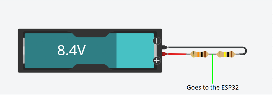
I did exactly as shown in the image and I'm getting values like 2000, 2300, ...
The code resumes on this line:
Serial.println(analogReadMilliVolts(32))
So if the other one is 10k, you are giving >7V to Esp pin....
If you didn't fry the pin yet you could try to swap the resistors.
Yeah, I noticed that, hope I didn't burned it
I just can't understand how I should wire the resisitors

It'll give you what resistor to put on top (R1) and so forth.