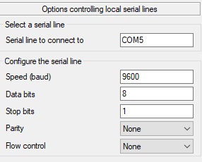
Usually, setting RS232 comms parameters involves settings in both devices - you'll need to navigate menus on the scale to set it to 'no handshaking', and you'll need to change Putty to none(that's likely a setting on the screen you included above). If you then have the same communication, you're away to the races, because the Arduino expects no handshake, software or hardware.
C
Your screenshot of putty in post #37 shows the handshaking set to XON/XOFF. Use the dropdown to change it to NONE. Then make sure that you can still receive the weight in putty as before. If you can, then your scales are likely not using any handshaking.
NOTE: we are now at post #42 in trying to help you and i cannot see that you have determined which pin on the RS232-TTL module you should be using to receive the data from the scales - either the one marked TXD or the one marked RXD.
You've switched from UNO to MEGA2560 and I don't see any progress has been made. Perhaps i'm not explaining in enough detail to help you further.
@markd833 - thanks again for your help.
I have tried to login into the COM without handshaking and I am receiving the data properly.
I've tried what you told me, and I cannot see any data incoming to the Serial even from Serial1, Serial2, Serial3(I changed the pins accordingly).
Thanks!
Someone commented about 'even check'

Hi,
When choosing Parity: Even this is the results from putty:

and the results is the same for each item from the list: Odd/Even/Mark/Space.
Pin1 is GND and Pin5 is Data.
Do you have a DMM ?
I wonder how often it sends data, but what is the voltage at Pin5 when it's not sending? I'm wondering if the 3232 is necessary.
I saw before where you were receiving 'kg' at some point, but not now.
What do you mean by writing DMM?
The image which print kG Is from the putty shell I connected the scale through he usb cable
"Writing DMM" appears nowhere in my post.
Departing this topic.
DMM = Digital Multi Meter
AKA VOM volt ohm meter
or anything else capable of doing a continuity test, as well as measuring voltage
Blockquote
Yes I have multi meter, what I need to check?
@Eshk12 read the responses. Please. This is excruciating.
Although in this case it seems like it isn't ever not sending long enough to measure the resting voltage of the line.
a7
@alto777 @markd833,
I have tried to plug a LED to the TX/RX pin in the RS232-TTL module, and the LED is not turning on.
this is how I plugged it: (sorry for my bad painting technique)

does is say anything that related to the RS232-TTL?
That says the chip on your adapter is not generating the required +- 8.x volts it must do in order to make your adapter work. When not sending data, the txd pin must be at a mark voltage or +8.x volts. Even + 5 volts will work with RS-232.
there is a chip that you can recommend for me?
It might be saying your module pictured in #53 is faulty.
Or your LED is backwards or bad.
Or your 220 ohm resistor is 2.2 megohms.
Jump TX to RX and see if you get a loop back test to pass using PuTTY.
Test the LED and resistor with you 5 volts supply.
Test the 5 volts with your meter.
HTH
a7
I have checked with 3 RS232-TTL module and I have the same results.
I have checked the LED?(+resistor) with 5v from arduino and the LED turned on.
I was tried to swap between RX TO TX and TX TO RX and the LED remain off, it's could be an issue with the RS232-TTL module which does not fit to my purpose?
Jump TX to RX and see if you get a loop back test to pass using PuTTY.
I didn't understand what I need to do here, can you explain a bit more?
Just powering the module will give you a valid RS-232 voltage on the TX pin. You are connecting the negative power to the ground pin of the module?
Woah!
That module receives/sends 5V signals on the pin header, and receives/sends RS232 levels(+/- N volts) on the 9-pin prehistoric connector. So, if you power it (+5 and GND from the Arduino), your signals on the pin header will be 0/5, depending on the state of the connections on the 9-pin connector; one pin will be an input, unable to drive an LED, the other will be an output, and can drive an LED.
The problem is, the labelling of those boards is ambivalent. Is RX for the data being received from the Arduino, or received on the 9-pin side? That's where the confusion lies.
Do the following:
With NOTHING connected to the 9-pin connector,
Connect +5 and GND from your Arduino to the board.
Then wire the resistor/LED from the board's RX to GND. Does it light?
If not, reverse the LED pins. Does it light now?
If it lit in either case, this is a digital output, and should be wired to the Arduino RX.
If it did not light, then this is a digital input, and should be wired to the Arduino TX.
C
Thank you for your explaination.
I have powered the RS232 - TTL module with the arduino 5+v and GND.
After that I have connect the LED+Resistor to RX and TX that inside the RS232 - TTL.
when connected to TX the LED does not light.
when connected to RX the LED does light.
seem to have some progress ![]()