I recently switched over from a bulky, expensive ADC to an Arduino Uno to read voltages from a quadrant photodiode position sensor (Thorlabs PDQ80A) into LabVIEW, and I just realized that the sensor is outputting both positive and negative voltages. It's my understanding that the Arduino Uno only accepts positive voltages (I'm only getting positive values in LabVIEW). After doing some searching online I learned that it was possible to create a circuit to convert the negative voltage into positive, but I'm unclear on the details.
As you can see from the datasheet for the QPD, it outputs -2V to +2V from three pins. What I need is for the -2V to 2V range to be converted to the Arduino's 0V to 5V range for each of the three pins. Any help in designing a circuit to accomplish this would be greatly appreciated.
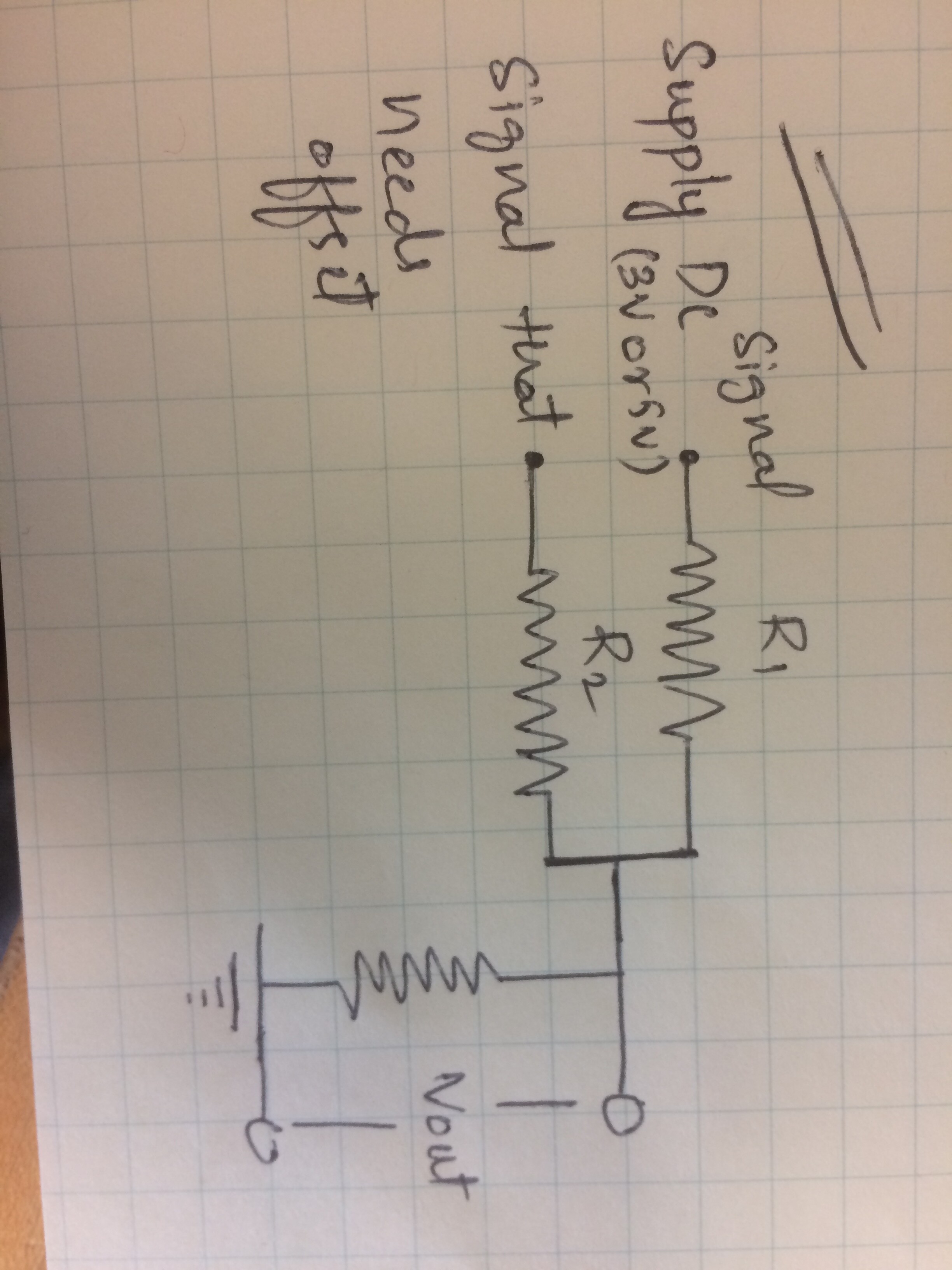
Run the signal thru a 10uF cap, to the junction of two 100K resistors between +5 & Gnd.
Signal should then sit at 2.5V nominally, and wiggle with the incoming analog signal.
You can use op-amp if you have one. However, you can use the circuit that crossroads have mentioned.
It should look like this. In the attached circuit diagram, I have used R1, R2, and R3 as 220 omega for my project. you can tinker with these resistors values so that you can understand yourself what is happening. Get a feel for it.
A voltage divider and coupling cap won't work for DC signals.
A resistor network puts DC on the sensor output.
Only opamps could solve this problem.
Leo..
To clamp (= shortcircuit, and not use) the negative going information of the sensor?
I'm sure that part is equally important as the positive half.
Leo..
Depending on the circuit you can power the sensor from virtual ground. Or maybe if it is part of something complicated you may power Arduino from virtual ground. So Arudino's GND will be -2V for the sensor.
That will work, assuming the sensor has a low output impedance and is ok with that 1mA.
If not, an opamp buffer with bipolar supply is still needed.
Leo..
Thanks for all the replies. I tried the circuit that meme suggested, but like some of you said it doesn't seem to work. I get a nominal value of about 1.65V, but the response I get from the sensor is much smaller than it was before. EDIT: It's also not dropping below 1.65V at any point, so I'm guessing it's still not receiving the negative half of the signal.
I'm going to talk to my adviser about trying the second circuit that Allan posted. I do believe the output impedance of the sensor is low, but I can't be sure seeing as it isn't mentioned on the data sheet. Is there a simple way to measure the impedance? Sorry if that's a stupid question; I'm a physicist, not an engineer.
If a +5volt and -5voltsupply is available, then it might be better to use a rail2rail opamp to amplify sensor output to 10volt peak/peak,
and use a 10k:10k divider at the output of the opamp, with fixed point connected to Arduino's 5volt rail.
That way you have a buffered sensor, and 0-5volt available for the Arduino.
Leo..
The LM358 would do OK with a 1mA pullup - it only needs to get to +2v.. And gives you the middle 4v out of the arduino's 5v adc range without risk of saturation. Good enough?
Instability of Arduino's default Aref could be the biggest problem.
I think my approach has a more stable (ratiometric) zero point, and increasing errors with larger sensor signals.
And your approach has linear errors over the whole range.
I would prefer a stable zero point.
Let me know what you think.
Leo..
Either way is linear with offset. At least my gain = 1. You rely on resistor tolerances.
How accurate is the +/- 2V sensor spec? It was pretty vague.
I'd rather lose a bit of dynamic range rather than risk overload. You could always cut the gain of your amp a bit. Tot up the worst case of 1% resistors to be safe .The opamp Voffset isn't very big compared to that.
And one could do with a precision +5 ref either way.
+/- 10% won't cut it.
Hmmmm
Wonder what the prof says?
But of course, he's a physicist and probably presumes all electronics is perfect.
Given the sensor costs a lot, it's worth getting it as good as one can.
By the way , it seems to have a response up to 100kHz - if the OP reckons he can get that out of an AT328, he's got another think coming!
Guys take a look at this document. In the page 4, there is a circuit I have used, it pretty much did the job.
But, I'll always suggest to go for op-amp, bcuz it can do so many things.
@Tracy order a op - amp if you don't have one, it's very cheap. But, I think ask your advisor, where can I get op-amp from university, people will give away. op-amp 741 is dual op amp. While TLC080 is a single supply op-amp. You can get these in your university from electrical department.