I’m working on a project with an Arduino Uno R4 to do a scientific experiment with biofeedback and have a couple of questions about safely interfacing analog sensors.
I’ve read conflicting info to do that using different types clamping diodes (Zenner, TVS, Schottky), resistors and voltage dividers, but I’m unsure how and which to implement these without distorting my signals.
1. Piezoelectric ECG Sensor on Analog In A0:
I’m using a piezoelectric sensor as an ECG input on analog pin A0 (spec sheet: http://m-cdn.adinstruments.com/product-data-cards/MLT1010-DCW-15A.pdf). The signal typically ranges from 200 to 500 mV, but during setup or accidental bumps (like tapping the table), it can briefly spike as high as ±10V. I want to make sure these brief overvoltage events don’t damage the Arduino, while still allowing me to accurately read the normal signal range.
Note that while trying to measure the current, I find about 1uA (which seems very low?), thus I’m wondering if it’s even necessary to protect the A0 pin, but since I will be using this for a scientific experiment I want to make sure my Arduino is safe and reliable on the long run.
-> What’s the best way, if necessary, to protect the analog input from these spikes without distorting the small ECG signal?
2. Magnetometer Sensor (Analog Output, -12V to +12V):
I also have a magnetometer sensor that outputs a voltage depending on the distance between two magnets. Its output can swing from -12V to +12V. I’m already using a voltage divider to reduce the range by a factor of 5, so the Arduino would see a maximum of about ±2.4V.
However, I don’t need to read the negative voltages, and I’m concerned that even divided, the negative voltages could damage the Arduino.
-> Is there a simple way to ensure that any voltage below 0V is safely clamped to ground, so the Arduino never sees a negative voltage?
-> Is it better to bias the signal so that 0V from the sensor maps to 0V (or a small positive voltage) on the Arduino, perhaps using a voltage reference or battery?
Thanks a lot in advance for your advice and suggestions!
If you have any circuit diagrams, part recommendations, or practical tips, it would be a huge help.
Clamping diodes is choice#1.
Zeners/TVS diodes distort near their zener voltage, because their knee-point is not sharp enough.
External Schottky clamping diodes, to help the internal ones, could leak too much if the source impedance is high (sensor#1).
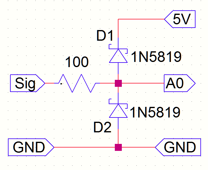
For small signals <500mV, you could try two 1N4148 diodes between pin and ground, back2back (anti-parallel).
For that -12 to +12volt signal you could use a three-resistor voltage divider, to convert to 0-5volt
Leo..
The first diagram with a 5.1volt zener is sort of useless.
Remember that max input voltage is not 5volt. It's "VCC+0.3volt"
The first diagram gives no protection when the Arduino happens to be off (when VCC=0volt).
Leo..
Thanks so much for all your valuable input and advice! This is really helpful.
I have a couple of follow-up questions based on your suggestions:
For Sensor #1 (Piezo):
Okay, so using 1N4148 diodes seems the best option. Is this a standard type, or are there specific versions I should look for my Voltage range ? Also (sorry if this is a basic question!), how exactly does the 1N4148 diode circuit ensure it clamps voltages specifically near 0V and 5V?
For Sensor #2 (Magnetometer):
Instead of building/ordering a 3R voltage divider, since I already have a 0-25V divider and don't need to measure the negative voltages, could I just add a single diode (same as piezo? () to clamp/block any voltage that goes below 0V?
Also, I read it's always good to add a resistor in a circuit to make it safe, should I consider that in any of these 2 cases ?
Yes but as I said I don’t need the data of the negative V, only the positive, thus my question if I can use a diode for that as well instead?
Also could you confirm if I can just use any TN4148 diodes for both circuit & if I should add a resistor before ?
You might need a Schottky diode, to keep clamping voltage below 0.3volt.
Tell us more about that magnetometer source.
A diode of course shorts that source voltage. Would that be a problem.
The function of a series resistor is to limit that short circuit current to a safe value (for source and diode).
Leo..
Magnetometer :
The magnetometer is amplified to produce a signal between 0 and 12V depending on how close 2 magnets are. However, if they are out of their operating range and come too close, they can go down to -12V. Thus I want a way to prevent any negative voltage from going in the Analog input of the Arduino.
Piezo:
Could you confirm if I can just use any TN4148 diodes (or how do I make sure they clamp voltage specifically near 0V and 5V?
When using a 1N4148 as clamping diode, then the input pin can swing between -0.7volt and 5.7volt.
The positive clamp dumps excess current on the 5volt supply rail. You must know how much current the source can deliver, to know if that will be a problem.
Leo..
However, concerning the diode type, if the Schottky diodes have a lower threshold, why should I use a 1N4148 for the piezo sensor and not a Schottky? Also, should the 2 diodes of the piezo, do you confirm they should be in parallel (not in series)?
As for the Magnetometer, do I only need to connect a Schottky anode to the A0 pin and the cathode to GND to discard the negative values (+ eventual resistor if current is too large, i will check) ?
I don't know the internals of the sensors you have.
Schottky diodes have a lower threshold voltage, but also more internal leakage.
That could be a problem for a piezo sensor.
The piezo sensor should only have a 1Megohm resistor across.
Nothing else should be needed (piezo currents are very small).
It's unlikely they can damage a pin, unless you maybe hit them with great force.
Leo..
It still needs a 1Megohm load across the piezo, as mentioned in the datasheet.
I would use a 2*2.2Meg voltage divider, to bias the sensor mid-voltage, so negative going sensor data can also be measured.
Leo..
As mentioned, I really don't want to measure negative voltage, but only a small range of positive voltage, and since the DAC pin of the R4 can only measure with 8-bit precision, I want to maximise the precision of a measure within the positive range...