Hi to everybody!
I would like to read the 7 bit ascii data with my arduino, and translate it in text.
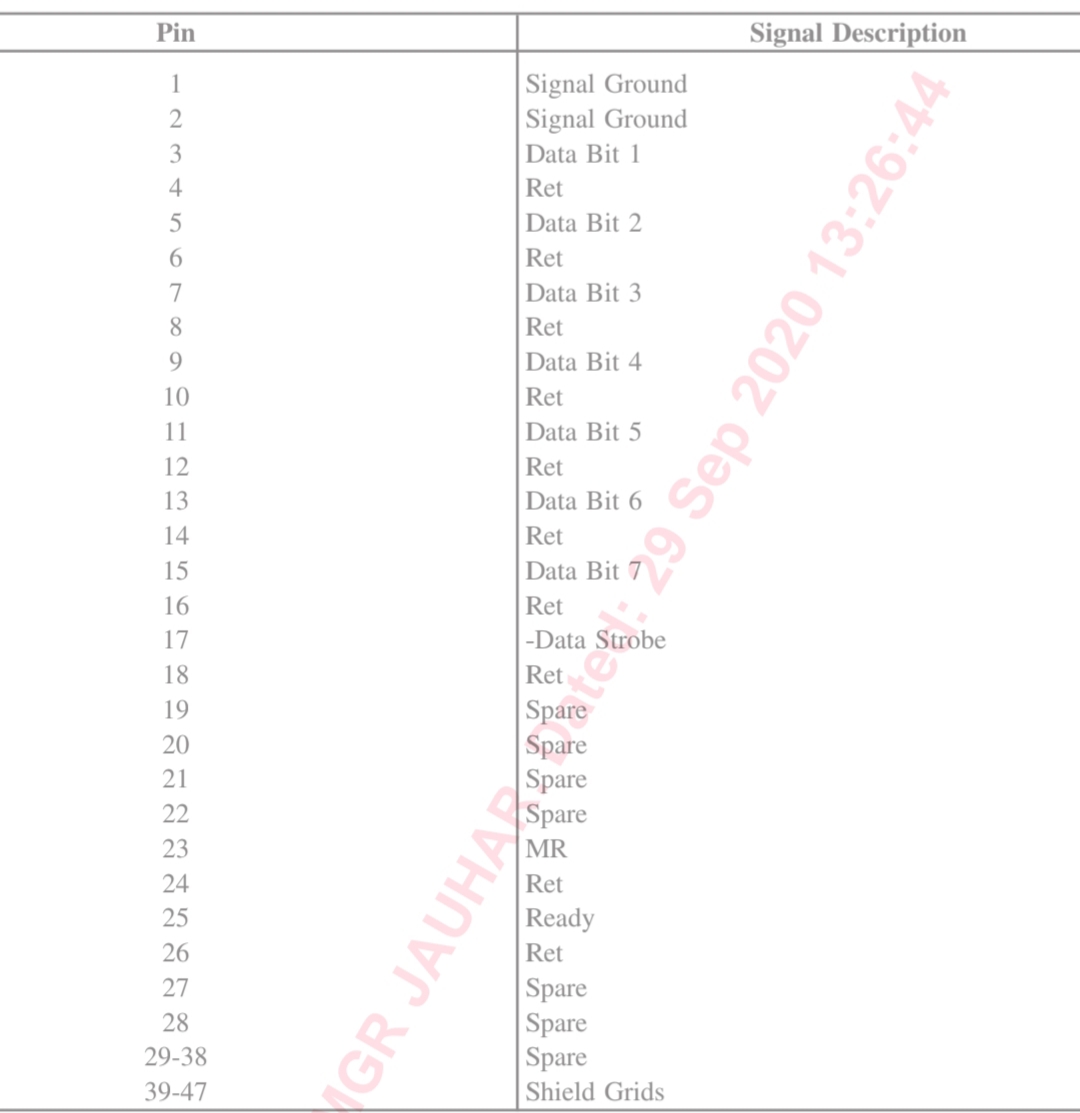
need program for that i am uploading data sheet of connector and pics ,if any one can guide and help in this i would be greatful.. i want to change old dot matrix printer to have data in new computer through COM port(serial )
thanks mate...is this code able to convert ASCII Bits into character form? or we have to compare it some look table or n will it be able to save it in a text file?
skyz007:
thanks mate...is this code able to convert ASCII Bits into character form? or we have to compare it some look table or n will it be able to save it in a text file?
Perhaps some some history lesson would help.
ASCII is and always has been 7 bits. No translation is necessary. Just read all the 7 pins you have the cable connected to and put each read value into the corresponding bit of a single byte. Magically you have the ASCII character that was sent from your device. The left-most bit of the byte will always be 0.
Paul
skyz007:
thanks mate...is this code able to convert ASCII Bits into character form? or we have to compare it some look table or n will it be able to save it in a text file?
As Paul said, the translation is automagic.
The code supplied won't save the text to a file (I assume you mean on an SD card) but it wouldn't be hard to add.
You could probably set up a terminal program (Putty maybe) to save incoming text to a file on a PC.
Just in case it wasn't clear from my rushed commenting:
const uint8_t grpinData[7] = { 37, 36, 35, 34, 33, 32, 31 }; //port C 0 through 6
The mapping from connector pins to Mega pins would be:
Circular            Mega        Signal
Connector Pin       Pin         Name
-------------       ------      -----------------
    3                37         Data Bit '1'
    5                36         Data Bit '2'
    7                35         Data Bit '3'
    9                34         Data Bit '4'
    11               33         Data Bit '5'
    13               32         Data Bit '6'
    15               31         Data Bit '7'
    17               18         nData Strobe
    23               3          MR (master reset?)
    25               2          Ready
    1                GND        Ground (connect as many 'Ret' pins as you can)
    2                GND...
Before getting too far ahead of things, give it a try as-is to see if, as a proof of concept, it works.
To be logically complete and match up with the old parallel port logic, there should be an ACK or acknowledgement pin so you can tell the device that you have received and processed all of the current data signals. There are a couple of "ready" pins that are kind of left with no purpose, so one of them may be the acknowledgement pin.
That's right, the "ready" pin 25, will probably halt transmission from the device. So you can signal the device to wait if your RX buffer gets too full.
For this project the Mega was nice because it brings full 8-bit ports to the GPIO pins. The Uno doesn't so it means instead of a single PORTx access to read the data during the strobe ISR I need to read two.
The code below uses the 6-bits of port C (aka A0..A5) and bit 0 of port B (aka 8) for data bits 0 through 5 and bit 6 respectively.
Anyway, check all the pin assignments and try the below on an Uno:
/*
 * Target   : Uno R3
 * File     : dot_matrix_printer.ino
 */

#define BUFF_SIZE       256
#define BUFF_SIZE_MASK  (BUFF_SIZE - 1)

const uint8_t pinStrobe = 2;        //falling edge of strobe
const uint8_t pinMR = 3;            //rising edge of reset
const uint8_t grpinData[7] =
{
    A0,         //data bit 0
    A1,         //data bit 1
    A2,         //data bit 2
    A3,         //data bit 3
    A4,         //data bit 4
    A5,         //data bit 5
    8           //data bit 6

};    //port C 0..5 and PB0

const uint8_t pinReady = 9;

volatile uint8_t
    rxBuffer[BUFF_SIZE];
uint8_t
    headPtr,
    tailPtr;

HardwareSerial *Console = (HardwareSerial *)&Serial;

void setup()
{
    Console->begin( 115200 );

    pinMode( pinReady, OUTPUT );
    pinMode( pinStrobe, INPUT );
    pinMode( pinMR, INPUT );
    for( uint8_t i=0; i<7; i++ )
        pinMode( grpinData[i], INPUT );

    //data is latched on falling edge of strobe
    attachInterrupt( digitalPinToInterrupt( pinStrobe ), isrStrobe, FALLING );

    //not sure if we care about master reset (I assume that's what MR is)
    attachInterrupt( digitalPinToInterrupt( pinMR ), isrReset, RISING );

    //circular buffer for received characters
    headPtr = 0;
    tailPtr = 0;

}//setup

void loop()
{
    //if the head and tail pointers aren't the same...
    if( tailPtr != headPtr )
    {
        //we're received data into the circ buffer
        while( tailPtr != headPtr )
        {
            //write it to the console and repeat until the tail == head
            Console->write( rxBuffer[tailPtr] );
            tailPtr = (tailPtr + 1) & BUFF_SIZE_MASK;

        }//while

    }//if

}//loop

void isrStrobe( void )
{
    //indicate busy

    digitalWrite( pinReady, LOW ) ;
    //grab the data and put in into the circ buffer
    // PC0 bit  0
    // PC1      1
    // PC2      2
    // PC3      3
    // PC4      4
    // PC5      5
    // PB0      6 (if '1' we OR the rxBuffer value with 0x40 to give bit 6)
    rxBuffer[headPtr] = (PINC | ((PINB & 0x01) ? 0x40:0x00)) & 0x7F;
    //bump the head pointer
    headPtr = (headPtr + 1) & BUFF_SIZE_MASK;
    //signal ready for more
    digitalWrite( pinReady, HIGH ) ;

}//isrStrobe

void isrReset( void )
{
    //again, not sure if needed. Just reset the head & tail pointers
    digitalWrite( pinReady, LOW ) ;
    headPtr = 0;
    tailPtr = 0;
    digitalWrite( pinReady, HIGH ) ;

}//isrReset
Paul_KD7HB:
To be logically complete and match up with the old parallel port logic, there should be an ACK or acknowledgement pin so you can tell the device that you have received and processed all of the current data signals. There are a couple of "ready" pins that are kind of left with no purpose, so one of them may be the acknowledgement pin.
I was kind of weirded out by the lack of an ACK pin and only saw one READY pin in the image the OP supplied.
I have busy high during the ISR but can easily change it to go high when the head nears the tail pointer and go low when a sufficient gap exists again.
I'm curious to see if the OP can try this and post results to see if it's feasible and what other changes would be needed.
Also curious if the printer he's emulating supports any escape sequences (which are not accounted for in this code...)
Blackfin:
I was kind of weirded out by the lack of an ACK pin and only saw one READY pin in the image the OP supplied.
I have busy high during the ISR but can easily change it to go high when the head nears the tail pointer and go low when a sufficient gap exists again.
I'm curious to see if the OP can try this and post results to see if it's feasible and what other changes would be needed.
Also curious if the printer he's emulating supports any escape sequences (which are not accounted for in this code...)
The "ready" pin and the "MR" pins may be the ACK pin or the "ready" may be there just to tell the printer the data source is connected and powered, while the MR pin may be the ack.
I haven't heard of escape sequences since the 1970-1980's. Very seldom used them!
I am confused about what the OP is really trying to do. Is he looking at data from a computer that is being sent to a printer, or is he getting data from a computer and trying to print it on an ancient printer?
Paul
Paul_KD7HB:
The "ready" pin and the "MR" pins may be the ACK pin or the "ready" may be there just to tell the printer the data source is connected and powered, while the MR pin may be the ack.
It'd be nice if the OP could supply a make and model number on that printer. Judging by that connector it's probably 60s or 70s vintage but there may be a full datasheet available that would clear that up.
I haven't heard of escape sequences since the 1970-1980's. Very seldom used them!
Heh. True. But look at that connector! So old...
I am confused about what the OP is really trying to do. Is he looking at data from a computer that is being sent to a printer, or is he getting data from a computer and trying to print it on an ancient printer?
Paul
I assumed (hopefully correctly) that the OP wants to intercept data being sent to the printer and print it to a serial monitor and/or saved to file.
Blackfin:
It'd be nice if the OP could supply a make and model number on that printer. Judging by that connector it's probably 60s or 70s vintage but there may be a full datasheet available that would clear that up.
Heh. True. But look at that connector! So old...
assumed (hopefully correctly) that the OP wants to intercept data being sent to the printer and print it to a serial monitor and/or saved to file.
i am sharing more details with you can u please give me ur email id
skyz007:
i am sharing more details with you can u please give me ur email id
You said "i am trying to get the data which is being sent by system to an old dot matrix printer.. i want to extract that data and save into a text file."
Tell me if I have this right:
You have a computer.
You have this old printer.
There is a cable interconnecting the two.
You want to "break into" the cable and sniff the data (etc) lines so that everything sent to the printer is "heard' by the Arduino and sent out the serial port to a(nother?) PC where it can be saved to file?
If so, did you try the Uno sketch I posted earlier?
If not, please concisely describe what you are trying to do.
Blackfin:
You said "i am trying to get the data which is being sent by system to an old dot matrix printer.. i want to extract that data and save into a text file."
Tell me if I have this right:
You have a computer.
You have this old printer.
There is a cable interconnecting the two.
You want to "break into" the cable and sniff the data (etc) lines so that everything sent to the printer is "heard' by the Arduino and sent out the serial port to a(nother?) PC where it can be saved to file?
If so, did you try the Uno sketch I posted earlier?
If not, please concisely describe what you are trying to do.
exactly u got that right bro...i will let u know tomorow after trying ur UNO code ...