I have a 0-5v PWM signal coming from a Laser controller, and I am trying to read that voltage and display it on a screen.
The ADC on this processor is 0-3.3v. Therefore I have a voltage divider on the PWM signal with a couple of resistors and this lowered the output to 0-3v.
I have tested the PWM output with a multimeter and indeed the voltage does increment correctly between 0-3v, depending on the 0-100% power signal I send to my laser.
But, my analogRead is basically only showing on/off and I cannot see why.
It's huge code, so here are the basics:
#define laserPWMread  A6

unsigned long PWMreadmillis;
int  laserPower;


void setup(void) {
  analogWriteResolution(10);                                // This was just to see if it helped
  pinMode(laserPWMread, INPUT);

  PWMreadmillis = millis();
}


void loop() {

  unsigned long currentMillis = millis();

  laserPower = analogRead(laserPWMread);

  if (currentMillis - PWMreadmillis > 500) {

    laserPower = analogRead(laserPWMread);

    Serial.println(laserPower);
    PWMreadmillis = millis();
  }
}
Any ideas why I only ever get <10 or >800 ish? Never anything in the middle.
I am constantly reading the ADC as I thought maybe I was missing samples by only checking the ADC every .5 seconds (it used to be inside the time update loop).
But, no difference.
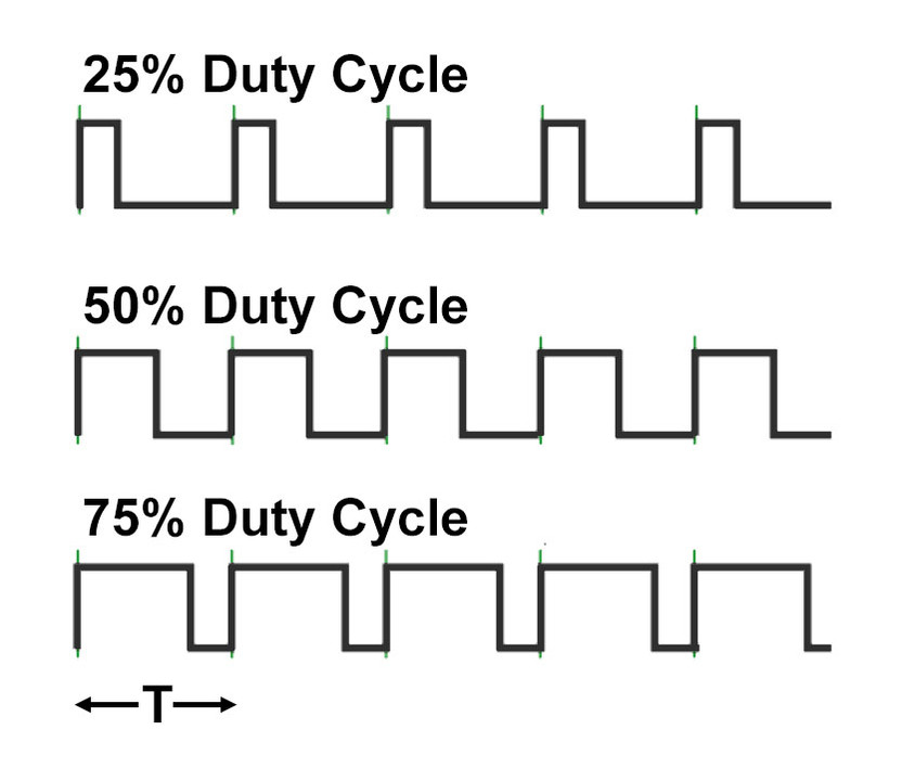
The PWM signal that you are measuring is switching rapidly between 0V and 3V (after the potential divider).
When you do an analogRead() you are measuring the instantaneous value of the input signal, so it is always going to be either 3V or 0V (unless you happen to catch a rising or falling edge).
A multimeter works differently. It takes its readings at a slow rate and responds to the average voltage during its sampling period.
You can't count on that. Different meters work differently. You might get an in-between reading that's not necessarily an average or the readings may jump-around, etc.
The inertia of an old-fashion analog meter movement will do a good a job of averaging,
Yes DVDdoug, I agree that is the case, but as stevolution2023 said he could see the voltage vary as expected when using his multimeter I gave him the "simplified" answer.
One way is to measure the incoming PWM pulse widths using the Arduino micros() function together with interrupts. This measures the pulse widths in microseconds and is accurate to around 4us on AVR mirocontrollers and 1us on ARM based ones.
The interrupt service rountine measures the time difference between the high and low going pulse edges:
// Sketch to calculate pulsewidth from an input signal in microseconds

#define INPUT_PIN 10                      // Arduino input pin number

volatile unsigned long isrPulsewidth;     // Define Interrupt Service Routine (ISR) pulsewidth
unsigned long pulseWidth;                 // Define Pulsewidth variable

void setup()
{
  pinMode(INPUT_PIN, INPUT);              // Set the input pin
  attachInterrupt(digitalPinToInterrupt(INPUT_PIN), calcPulsewidth, CHANGE);   // Run the calcPulsewidth function on signal CHANGE
}

void loop()
{
  noInterrupts();                         // Turn off interrupts
  pulseWidth = isrPulsewidth;             // Copy the isr pulsewidth to the pulsewidth variable
  interrupts();                           // Turn on interrupts
  // Work with pulsewidth here ...
  // ...
}

void calcPulsewidth()                    // Interrupt Service Routine (ISR)
{
  static unsigned long pulseStartTime;   // Start time variable

  if (digitalRead(INPUT_PIN) == HIGH)    // If the change was a RISING edge
  {
    pulseStartTime = micros();           // Store the start time (in microseconds)
  }
  else                                   // If the change was a FALLING edge
  {
    isrPulsewidth = micros() - pulseStartTime;    // Calculate the pulsewidth
  }
}
If it's necessary to read faster pulsewidths, microcontroller specific solutions exist, but require delving into register manipulation.