Hey guys im building a flow bench and would like to use a pair of automotive flow sensors "MAF" sensors.
I want to poll both sensors analog values and record them, But I am having issues with the wiring.
Here is the sensors internal diagram:
[If anyone wants to explain this further that would be appreciated, i understand that its a wheatstone bridge used to measure the variable hot film resistor but it seems there are 2 variable resistors? is this to help trim the output based on the temperature? why would you want two sensors to measure temperature? what is the op-amp on the left doing? and the power transistor?]
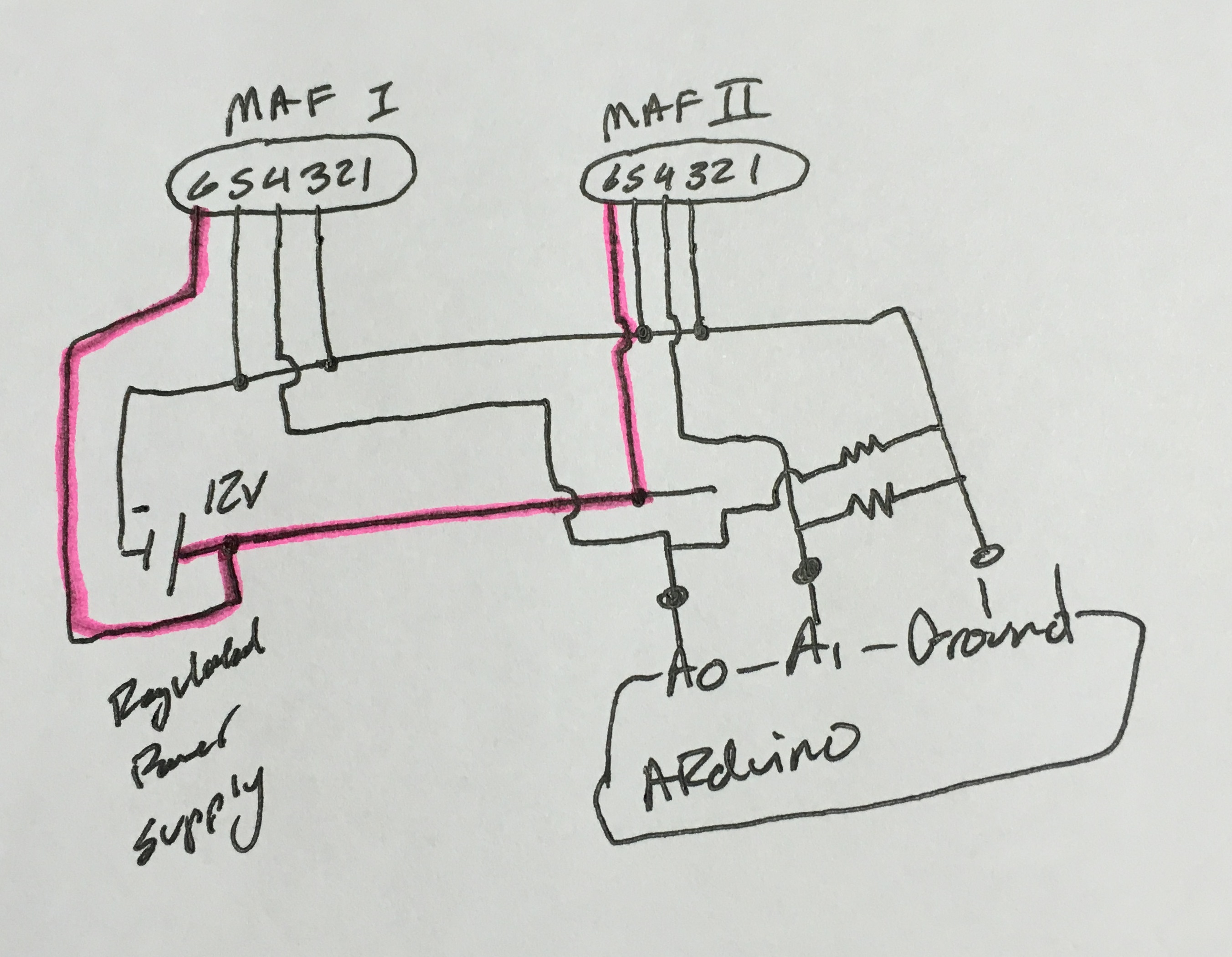
Here is the wiring on the sensor. We will be using pins 3,4,5,6.
Pin 6 will need 12v power. I will supply this with a regulated 12v power supply, pin 5 will go to regulated power supply ground
4 is the sensor return to the analog pin.
HERE IS WHERE I GET CONFUSED: What do I do for ground wires? tie all of them together?
Also inside the oem ecu they use pull down resistor on the MAF signal line. Do i need to replicate this for any reason? how would i?