hello forum. i am in the process of building a simple diagnostic for my car.
all the sensors I have used to get info, are additional, so i haven't interfered with any of the cars sensors, expect 2 : crankshaft position and throttle position sensor.
crankshaft position : provides a 12v pulse, 4 times per engine revolution. i use a simple optocoupler, with 1Kohm resistor, to read that signal.
Thtottle position sensor: 0 - 5v proportional to how much throttle is applied.
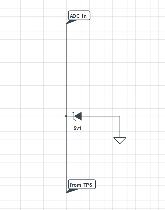
I have attached the "Schemantic"... very simple....
so here is the problem : when i have the diagnostic connected, the car behaves strange. meaning. "i press the throttle, and the engine, either lags to rev up , OR it starts to rev up, then stops, then starts etc... "
i don't believe that the problem resides with the Crankshaft sensor, because i have done the same thing in previous version of the diagnostic, and all was fine.
so... i guess that the problem is , the way i read the TPS. i thought that the arduino analog input where high impedence, so it wouldent interfere with the car ECU...
What's the voltage range on the TPS without the zener and disconnected from the Arduino?
If its 0-12V, you could replace the zener with a series connected 15K resistor which would offer 0-20VDC protection on the analog input. Could then add a 0.1µF (100nF) capacitor from ADC in to GND which will improve measurement accuracy and stability.
EDIT: Even if its still 0-5V, I would try the same thing, except using a 10K resistor.
Yep ! The output of the tps is 0-5v without my zener ! I installed the 10k resistor and it reduced the problem very much !!
I suspect that the problem is that my diagnostic , is inducing noise in the sensor (they are grounded in diferent places ... ) and the 10k reduces that noise...
But i still can see some problems.. (not much tho ) would a larger value resistor work better ?? ( i know that i would have to wait more for the analogpins to charge that way, but i am ok with that !!)
What else could i do ??
P.s : something stupid. Would a diode and a 10k i. Serries , from tps to A0 , solve this ?? ( and i wouls compestate in the code for the voltage drop )
Without a scope its hard to know. It could be that the 10K is to high. It could be eliminating the noise, but also slowing down the rise/fall time of the signal to much for communication. It might be beneficial to try a series 1K resistor, then lower value to see what works best.
Wrapping the power connections through a ferrite core will help to improve noise immunity.
I see.... BUT , the TPS is just a potentiometer... So i wouldent think that the 10k would slow tge rise of the signals ... would an op amp buffer solve it better ???
I suspect that the problem is that my diagnostic , is inducing noise in the sensor (they are grounded in diferent places ... ) and the 10k reduces that noise...
I think the main problem at this point is noise through the GND and Vin connections to the Arduino.
A ferrite core could resolve this ... 3-5 turns of the GND and the Vin wire through the core should be all that's needed.
It would provide a stronger signal and probably wouldn't let the noise through, but if the problem is due to noise on the power connections, the noise issue will remain. I would try using a ferrite core first ... its a common solution for this type of problem.
Without knowing the R of the pot or the impedance of the original sensor electronics, it could be that you are loading the vehicle signal by connecting your circuit.
If that is the case, try a larger value R to your input. As this will slow down your ADC, do a couple of reads before accepting the ADC value.