I am trying to measure the output current of my sensor using arduino.
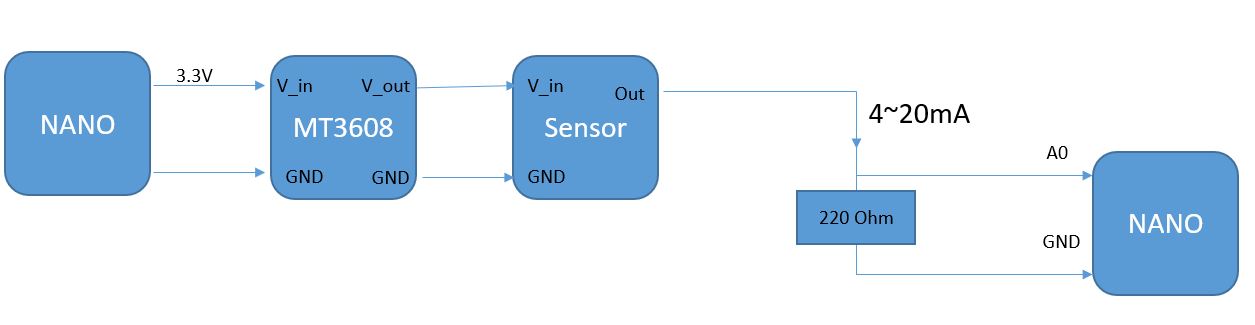
Attached you can find the circuit that should work to my knowledge, however for some reason the reading values does not change at all.
Below is the code :
void setup() {
  // initialize serial communication at 9600 bits per second:
  Serial.begin(9600);
}

// the loop routine runs over and over again forever:
void loop() {
  // read the input on analog pin 0:
  int sensorValue = analogRead(A0);
  // Convert the analog reading (which goes from 0 - 1023) to a voltage (0 - 5V):

  float voltage = sensorValue * (5 / 1023.0);
  // print out the value you read:
  Serial.println(sensorValue);
}
You need to be careful here, what is the voltage supply of your sensor? please post a link to that sensor.
Problem with Nano is it's AREF voltage(the voltage it compares analog voltages to) is different depending on how it is powered.
If powered from USB socket, the AREF will be about 4.7V, if powered from 5V pin, AREF will be that voltage, if powered from VIN pin, AREF will be near 5V. You need to know that to get accurate readings. Also, be very careful NOT to apply more than VCC to an input pin, that's why I ask about sensor voltage.
JCA34F:
You need to be careful here, what is the voltage supply of your sensor? please post a link to that sensor.
Problem with Nano is it's AREF voltage(the voltage it compares analog voltages to) is different depending on how it is powered.
If powered from USB socket, the AREF will be about 4.7V, if powered from 5V pin, AREF will be that voltage, if powered from VIN pin, AREF will be near 5V. You need to know that to get accurate readings. Also, be very careful NOT to apply more than VCC to an input pin, that's why I ask about sensor voltage.
Link to the sensor : https://cdn.sick.com/media/pdf/4/84/384/dataSheet_BCG05-K1KM01PP_6039745_en.pdf
The supply voltage of the sensor is 19 -33 V. So I took 3.3V from nano and converted with a MT3608 DCDC converter to 24 V. The output of the sensor is current between 4-20mA. So I took another Nano to read it by converting it to correspond voltage value.
Why do you use a 3,3V Arduino when you want to use sensors in the 24V range. Pretty big up-convert. I see 2W for the sensor. Including DCDC losses that's almost 1A at 3,3V.
And the sensor outputs current, did you put that through a shunt resistor? An Arduino can't measure current directly, you need to convert it to voltage. If you put it through a 55Ω resistor the 20mA will correspond to 1,1V (aka, internal reference voltage of a ATmega328p.
If you didn't use a resistor and connected that sensor directly to the Arduino you might even have damaged the Arduino depending on the current the sensor was outputting.
septillion:
Why do you use a 3,3V Arduino when you want to use sensors in the 24V range. Pretty big up-convert. I see 2W for the sensor. Including DCDC losses that's almost 1A at 3,3V.
And the sensor outputs current, did you put that through a shunt resistor? An Arduino can't measure current directly, you need to convert it to voltage. If you put it through a 55Ω resistor the 20mA will correspond to 1,1V (aka, internal reference voltage of a ATmega328p.
If you didn't use a resistor and connected that sensor directly to the Arduino you might even have damaged the Arduino depending on the current the sensor was outputting.
Yes, the sensor consumes 2W. Since the supply voltage is 24V, the corresponding supply current is about 83mA. As far as I know, the pins of Nano can provice upto 200 mA. So I thought this must be enough for the sensor, isnt it ?
The arduino cannot measure current directly, so that's why I used 220 Ohm resistor ( attached figure ). With this 220 Ohm, the current from the sensor in the range 4-20mA, should be converted to 0.88- 4.4V. Am I right so far?
You completly forget the change from 3v3 to 24V you do with the DCDC converter! Yes, 2W is 83mA on the 24V side, but 2W is 600mA on the 3.3V side with 100% efficient conversion. Think 70% efficient is still pretty good but that already makes it 866mA!
Ah, yeah, forgot about the image:
Yes, 20mA through 220Ω gives you 4,4V. BUT, how is a 3,3V Arduino suppose to measure that? It can only go up to Vcc (and heck, above it can damage it).
And this relies on the sensor and the Arduino share the ground. We know nothing about the DCDC converter / rest of the circuit so we just have to assume.
And this still leaves the massive power consumption on the 3,3V side.
Oh...So I only provided 0.66W power to the sensor (100% conversion assumed)...But I only can provide 1W even with Mega2560. So maybe arduino is not suitable for this sensor.
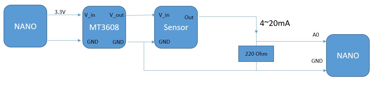
Why should the sensor and arduino share the same ground? Do you mean the arduino that is reading the output current or the one providing supply voltage ? I completed the circuit with DCDC converter. Could you have a look ?
No, Arduino's are terrible at supping power. It would make much more sense to do it the other way around. Get yourself a proper 24V supply and use a DCDC converter to go to 3,3V (or 5V because a Arduino Mega isn't a 3,3V device).
You can only measure voltage across something. So when the Arduino needs to read a voltage on it's pin that's in reference with GND. Also, the sensor will try to let that 20mA flow to it's GND. So they must be the same.
In your image, is the Nano on the left the same Nano as on the right?
Also, what Arduino are you actually using? You speak about Nano, Mega and 3,3V which all suggest something else.
PS WHY does this forum keep posting when I hit Preview sometimes!
Anything that you could recommend? Something similar to Arudino which can be integrated into a system easily?
You can only measure voltage across something. So when the Arduino needs to read a voltage on it's pin that's in reference with GND.
Oh, I see. Does the circuit look better now? The arduino on the left is different than the arduino on the right. I am using two arduinos, one for the supply and one for the reading.
Also, what Arduino are you actually using?
Currently, I am using Nanos. I spoke of Mega because it can provide 5V which Nano cannot. Apparently, Mega still wouldnt be enough for 2W power supply.
Like I said, all Arduino's are terrible at supplying current So swap one Arduino for whatever supply fits your needs and use a single Arduino (the one that suits the design) to do the task.
About the supply, does the whole circuit only consists of that sensor and a single Arduino? Or is more connected? If that's all I would just get myself a decent USB charger and use that to power that MT3808 to get 24V for the sensor and to power the Nano on it's Vcc pin. But I would switch to the internal 1,1V reference (or another fixed reference) instead of using Vcc as a reference so it's more stable*. That's why I suggested a 55Ω resistor but to have some headroom and an easy to get resistor 47Ω would do.
If it's a more complex system / more industrial I would get myself a nice 24V DIN-rail supply from Block or Meanwell or something. And use a DCDC converter to get 5V for the Arduino from that.
Talking about DCDC converters, unless they specify it it's pretty safe to assume they have a shared GND. Aka, the GND on the input side is just the same (aka just linked) as on the output. Or in other words, it basically is just a 3-pin device, In, Out and GND.
And in terms of powering I would pick the Nano. The Nano can be powered from 5V via it's Vcc pin while being connected to USB because it has a diode between USB power and Vcc. The Uno and Mega can not (although the design of some clones may differ) and can only be safely powered via Vin (or the Jack plug) while being connected to USB (which would require a volttage of >7, <12-ish).
Although it's more stable it might not be exact (same applies to the resistor), so you may need to do a calibration in software (or hardware).