Still having troubling reading data from my inclinometer. This is what I'm using:
esp8266 NodeMCU (but I have others if needed)
Inclinometer SOLAR-2-15-2-RS485
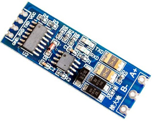
the module MAX485
For the inclinometer, I had the choice between RS232, RS485 and RS485 MODBUS outputs. For some reasons, I choose the second one. Please have a look here as, even if I'm not sure how to use them, they provide lots of info:
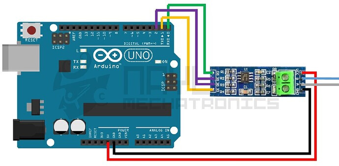
I did something like this, except that DI and R0 go to D5 and D6 on esp8266, and RE/DE go to D2:
My sketch is :
#include <SoftwareSerial.h>
#define SSerialRX        5  //Serial Receive pin
#define SSerialTX        6  //Serial Transmit pin
#define SSerialTxControl 2   //RS485 Direction control

#define RS485Transmit    HIGH
#define RS485Receive     LOW

SoftwareSerial RS485Serial(SSerialRX, SSerialTX); // RX, TX

int byteReceived;
int byteSend;

void setup()
{
  Serial.begin(9600);
  delay(500);

  pinMode(SSerialTxControl, OUTPUT);
  digitalWrite(SSerialTxControl, RS485Receive);  // Init Transceiver

  // Start the software serial port, to the inclinometer
  RS485Serial.begin(38400);   // set the data rate

}//--(end setup )---


void loop()
{
  if (RS485Serial.available())
   {
    byteReceived = RS485Serial.read();    // Read received byte
    Serial.println(byteReceived);        // Show on Serial Monitor
    delay(10);
   }

}
My goal is of course to extract X and Y axis angles but I don't know how to get them, even though I read the manual 3 times and I checked my wires 25 times.
In the manual, they give the Modbus Register Address (but that's not the one I chose), bytes data for reading the holding registers... but I'm not able to get any data.
Wrong microcontroller?! Wrong module?! Mistakes in my sketch?! I don't know anymore what to think. Please, I really need your help.
DI is where data transmitted from your ESP8266/UNO goes into the RS485 module. If DI is connected to D5, then SSerialTX should be set to 5.
Page 6 of the PDF you provided seems to list the commands you need. I'm thinking that you need to send a command in order to get a response.
Try sending the character string get---x and see what you get back. The response may be human readable ASCII text or binary depending on the interface setting.
see post #7 for RS485 using a Mega - the mega has the advantage of having hardware ports - there is also an example using an Arduino Due
I find it useful when working with RS485 to have a USB-RS485 dongle so I can monitor traffic on a PC
I suspect that, as your code stands, the test will fail. As I said previously, I think you may need to ask for the data, rather than just waiting for the sensor to send it.
Definitely agree with this. When nothing seems to work, one of these dongles is an excellent debugging tool. It also allows your PC to talk to the sensor so you can figure commands and responses etc, without constantly rebuilding your sketch.
Off the top of my head, try something like:
void loop()
{
  digitalWrite(SSerialTxControl, RS485Transmit);
  RS485Serial.println("get---x");
  RS485Serial.flush();
  digitalWrite(SSerialTxControl, RS485Receive);
  delay(100);

  if (RS485Serial.available())
   {
    byteReceived = RS485Serial.read();    // Read received byte
    Serial.println(byteReceived);        // Show on Serial Monitor
    delay(10);
   }
  delay(1000);
}
EDIT: looking at the commands, you may be able to issue these commands in your setup routine:
str1000
setcasc
That should tell the sensor to output the X and Y values continuously at 1 second intervals.
I tried that and I effectively have some outputs but it doesn't give any useful info. I had either "-1" or "9" or "4294967296" depending on the sketch. At least better than nothing.
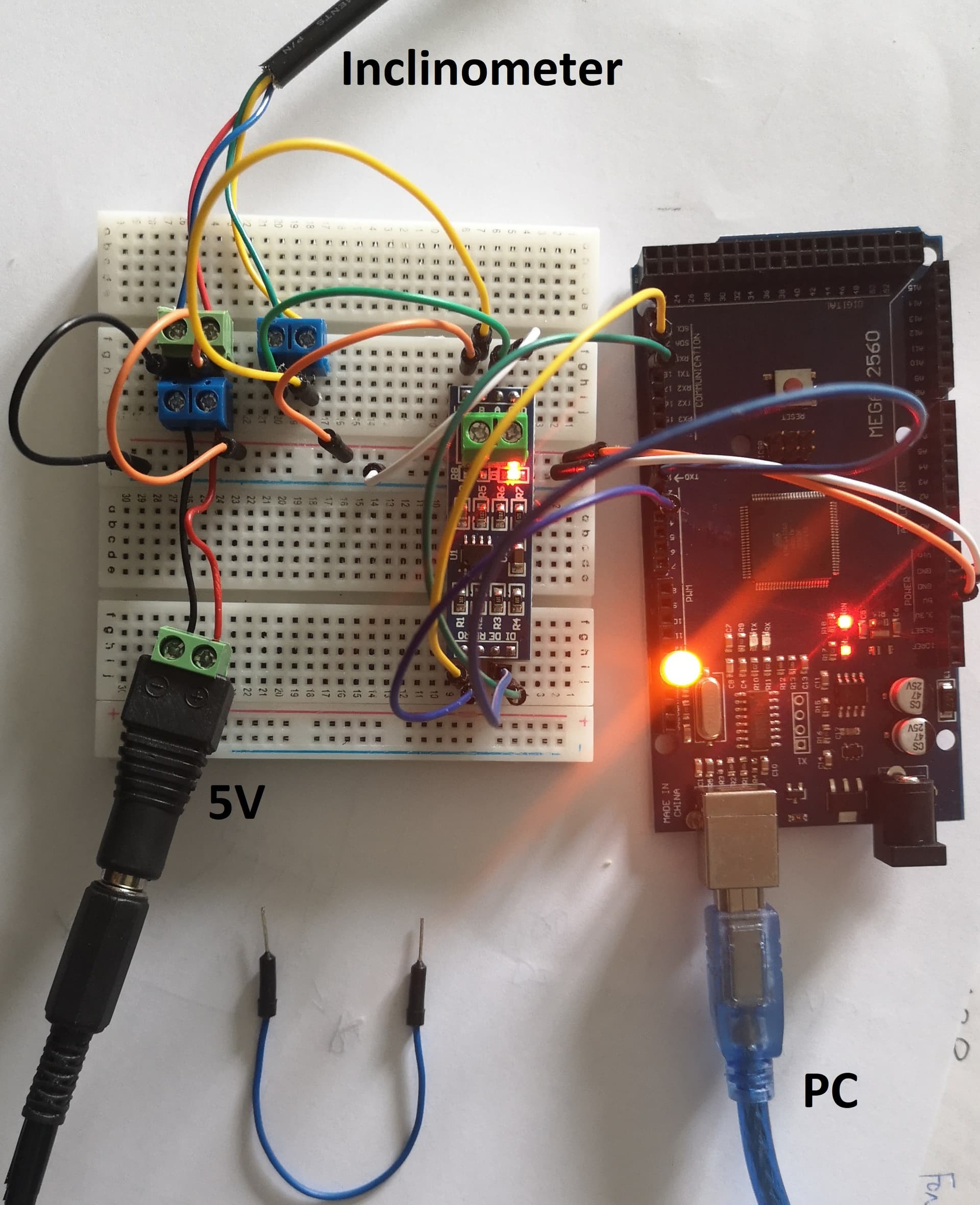
Inclino Yellow RS485 - -> B
Inclino Green RS485 + -> A
// RS485 using arduino mega Seial1 pins 18 and 19

#define RS485Serial Serial1   // hardware serial port on Mega
// connect RS485 DI and RO to Mega Serial1
//   Serial Receive pin 19  to RO
//   Serial Transmit pin 18 to DI
//   pin 3 is RS485 Direction control DE & RE jumpered together

#define SSerialTxControl 3   //RS485 Direction control DE & RE jumpered together
#define SSerialTxControl2 2   //RS485 Direction control DE & RE jumpered together

#define RS485Transmit    HIGH
#define RS485Receive     LOW

#define Pin13LED         13

void setup()   /****** SETUP: RUNS ONCE ******/
{
  while(!Serial);
  delay(1000);
  // Start the built-in serial port, probably to Serial Monitor
  Serial.begin(38400);
  Serial.println("Use Serial Monitor, type in upper window, ENTER");

  pinMode(Pin13LED, OUTPUT);
  pinMode(SSerialTxControl, OUTPUT);
  pinMode(SSerialTxControl2, OUTPUT);
  pinMode(2, OUTPUT);
  digitalWrite(2, HIGH);

  digitalWrite(SSerialTxControl, RS485Receive);  // Init Transceiver
  digitalWrite(SSerialTxControl2, RS485Receive);  // Init Transceiver
  // Start the RS485 serial port
  RS485Serial.begin(38400);   // set the data rate
}

void loop()
{
  digitalWrite(Pin13LED, HIGH);  // Show activity
  if (Serial.available())
  {
    digitalWrite(SSerialTxControl, RS485Transmit);  // Enable RS485 Transmit
    digitalWrite(SSerialTxControl2, RS485Transmit);  // Enable RS485 Transmit
    RS485Serial.write(Serial.read());          // Send byte to Remote Arduino
    digitalWrite(Pin13LED, LOW);  // Show activity
    RS485Serial.flush();    // wait for byte to be transmitted
    digitalWrite(SSerialTxControl, RS485Receive);  // Disable RS485 Transmit
    digitalWrite(SSerialTxControl2, RS485Receive);  // Disable RS485 Transmit
  }

  if (RS485Serial.available())  //Look for data from other Arduino
   {
    digitalWrite(Pin13LED, HIGH);  // Show activity
    Serial.write( RS485Serial.read());        // Show on Serial Monitor
    digitalWrite(Pin13LED, LOW);  // Show activity
   }
}
I'm ready to try any of your suggestions. I'm trying other things in the mean time.
Thanks to all of you
I suggest for now connect the SH-U11 USB-RS485 dongle to the Mega/MAX485 to check the basic system works - when it works connect the SOLAR-2-15-2-RS485
To add to what @horace suggest, I would use your USB-RS485 dongle on your PC and a simple terminal program.
Your connections would be like you say: A, B & GND. Sometimes it can be marked + & - instead of A & B. Try swapping them over. The GND would also be the GND of whatever you are powering the sensor with too.
You should be able to type in the commands from the manual on the terminal program and see the response from the sensor. Make sure you have the correct baud rate, parity, stop bits, line ending etc.
... if it works! I was not even able to get anything with that. Just to make sure, I've connected A and B of the USB-RS485 to A and B of the MAX485. And GND to GND. The rest (DI, RO...) was connected to the MEGA as before. And I used the same sketch as before.
Do you mean just the USB-RS485 dongle connected to the PC and the module MAX485, and the module connected to the MEGA as before?
Sorry guys but I need concrete examples with a scheme and a program to test. I'm not good at it and if you would have a link to send me, that would be great.
Just the PC, the USB-RS485 dongle and the sensor for now. That way you can figure out how to use the sensor before implementing your Arduino code. (see option 2 from @horace below).
the idea is to simplify the problem so you are only testing two components at a time
two ideas
was to connect the USB-CAN485 dongle direct to the Mega/MAX485 (A to A and B to B) and run the program you used in post #8 - set the all the baudrates to 9600 and you should be able to type on the Mega serial monitor and see it appear on the USB-RS485 dongle terminal etc etc
was to connect the USB-CAN485 dongle direct to the SOLAR-2-15-2-RS485 - set the USB-RS485 baudrate to the SOLAR-2-15-2-RS485 baudrate - do you know this? you should be able to communicate
Thanks @horace. Yes I did try both and I was not able to get any answer (according to the user guide, the baudrate for the SOLAR is 38400).
When I'm typing a command in the Serial monitor, I got no answer back
you first post mentioned a ESP8266 - have you given up on that and moved to the Mega?
could you upload a schematic of how you wired up the USB_RS485 dongle to the MAX485 module and the Mega?
do you have a multimeter? if so what voltages do you read on the A and B signals?
do you have an oscilloscope ? if so what do the A and B signals look like?
what software do you use on the PC to communicate with the USB_RS485 dongle?-
Hey guys,
I will be off the next 3 days and won't be able to work on that.
Before I go, I have to tell you I have good news! After reading the manual (I read it 2 months ago but I forgot), a friend told me the input voltage was 12-30V while I was using 5V!!!! I couldn't resist and quickly tested it again with 12V and guess what... it worked! I only had time to test it with the MEGA2560. I was able to get answers from different commands in the Serial monitor like "get---x" or "get---y"... I will try with the ESP8266 when I come back and let you know what I did.
Thanks a million
Back to work!
Thanks to both of you @horace and @markd833.
I'm now able to get what I want by typing for example "get---x" in the Serial Monitor. But it's not over !
What I would like to do now:
How to get this value X without typing the command in the Serial Monitor but instead I would like to include it in the code so it is displays every seconds for exemple ? I'm using the code in post #8.
I was not able to reproduce this using an ESP8266. So I guess I need to store the result of this command in a variable and send it to my ESP8266. Then I will treat it the same way as for my other connected sensors so I can send it by ftp to a distant server. How can I connect this ESP8266 to my actual scheme (see post #8 above). Ideally, I would like the esp8266 to ask for this value once every xx minutes... Is there a better way?
use millis() to measure elapsed time, e.g. transmits the value of data every second
void loop()
{
  static long timer=millis(), data=1;
  digitalWrite(Pin13LED, HIGH);  // Show activity
  if ((millis()-timer)>1000)
  {
    timer=millis();
    digitalWrite(SSerialTxControl, RS485Transmit);  // Enable RS485 Transmit
    digitalWrite(SSerialTxControl2, RS485Transmit);  // Enable RS485 Transmit
    RS485Serial.write(data++);          // Send byte to Remote Arduino
    Serial.println(data);
    digitalWrite(Pin13LED, LOW);  // Show activity
    RS485Serial.flush();    // wait for byte to be transmitted
    digitalWrite(SSerialTxControl, RS485Receive);  // Disable RS485 Transmit
    digitalWrite(SSerialTxControl2, RS485Receive);  // Disable RS485 Transmit
  }
static variables are used to ensure the value calculated in loop() is maintained for the next call otherwise it would be reset
if you wish to run the code of post #8 on an ESP8266 you will probably need to use SoftwareSerial