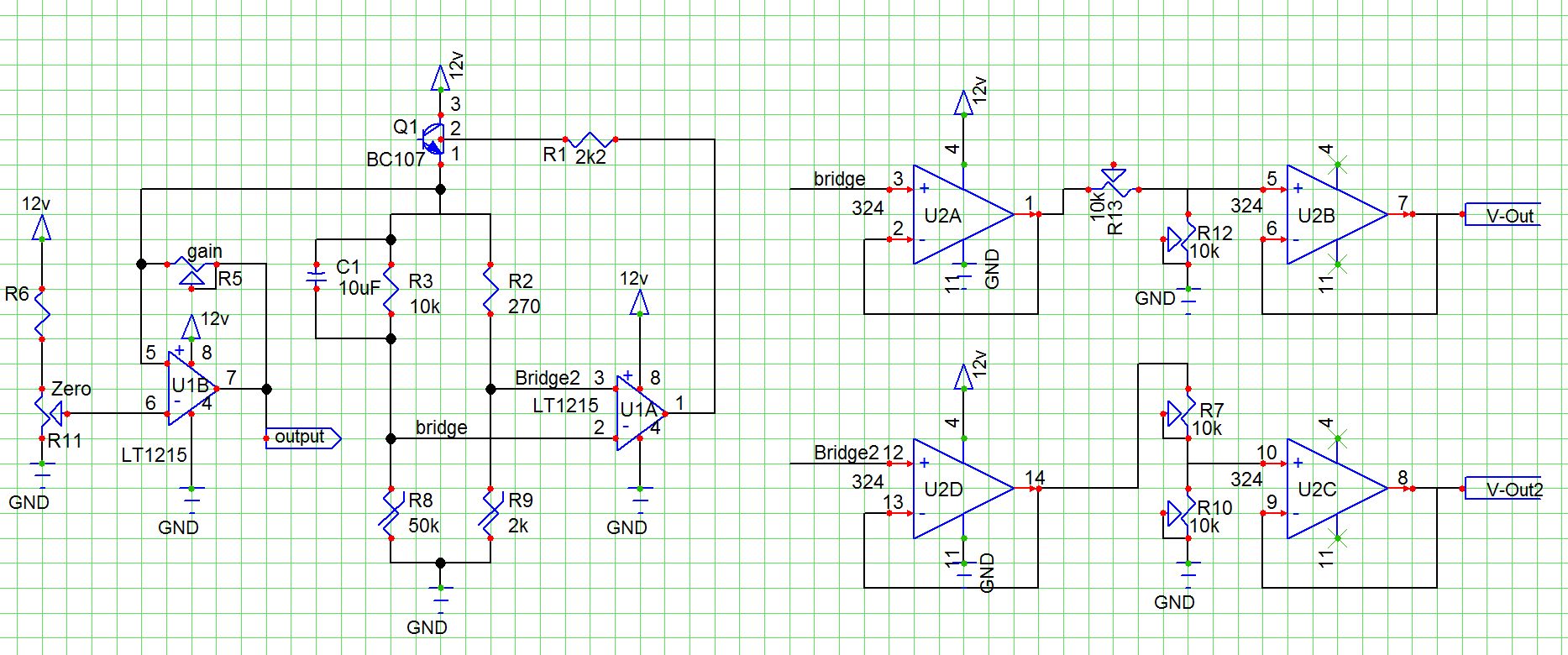
The left side has a zero and cal that are connected with what looks like a meter.
I am not sure if that is a physical connection.
Also zero and cal appear to be pots, again, not sure.
the note of U with the dot is only a test point for reading voltage in that part of the circuit.
lastly, there is a lone box on the left, possibly a resistor to set for a voltage divider for the zero pot.
The left side has a zero and cal that are connected with what looks like a meter.
I am not sure if that is a physical connection.
Yes, it's a meter. That is the whole point of the circuit, an anemometer.
dave-in-nj:
Also zero and cal appear to be pots, again, not sure.
Since they use the same general symbol as every other resistor in the diagram, that makes sense.
dave-in-nj:
the note of U with the dot is only a test point for reading voltage in that part of the circuit.
Well, it is actually a functional junction point. The components on the right of it are the circuit which gives you an output whose voltage value is - as per the graph - proportional to your wind speed. Except that it has a fixed offset. The components on the left are whatever you choose to connect in order to indicate that measurement, given that you have to cancel out the offset.
The use of the BC107 in the feedback loop give it a very low output impedance which permits you a wide choice of indicators which is why the component values to the left of the junction are not specified; they are left up to you. Given that you are posting this in the Arduino context, you might be going to use an Arduino to do this by attaching a voltage divider to "U" to feed the analog input of the Arduino. Your offset cancellation will then be in software and your only concern will be to provide a regulated and stabilised supply of 10 to 12 V - though the use of the op amp and emitter follower is intended to provide substantial independence of the supply voltage and it is only the offset voltage divider that will be affected by fluctuations. If the offset is corrected in software and you are not using the left hand side of the circuit, then it is only the ADC reference which needs to be accurate.
dave-in-nj:
lastly, there is a lone box on the left, possibly a resistor to set for a voltage divider for the zero pot.
this came from here.
Looks like a resistor, quacks like a resistor ...
Its presence implies the expectation that the offset voltage on "U" will be less than half of the 10 V. 4.5 V in fact according to the graph:
dave-in-nj:
Sounds like I would be well served to put that signal into the other half of the op-amp. Then add a zero and span adjustment for my needs.
Since the Analog inputs are 10 bit, I will want to try to use as much of that as I can.
Admirable intention, but the offset represents only one bit on the ADC and the accuracy of this device is no better than perhaps 5% (six bits) at the very best imaginable.
My goal is not high accuracy, but more of getting the output to fit the 5v span of the ADC.
This is more of a 'flow proven' sensor for an exhaust fan of a greenhouse.
if the blade is not spinning = no airflow
no power = no airflow.
but a bad blade and spinning motor means motor amps.
I also thought of a sail switch, just a target that gets pushed onto a microswitch, but this seems more high tech.
based on the graph, 0 to 20 m/s is about 4,000 FPM, or a VERY high power blower.
less than 1,000 FPM or about 5 m/s is closer to my goal. 800 FPM is my expected high speed fan output.
the output is logarithmic, so I hope to get a higher sensitivity in this range,
and more hope, that the 1+ volt output [per the graph] can be coaxed into something useable into an ADC.
I was looking into an ultrasonic anemometer, but that seemed just too high tech.
my biggest problem is insects, birds and spiders. I was hoping I could mount all the bits on a PCB so I would not have places that would attract the little critters and be something I could dust off with a soft brush. a raised thermistor to clear the board would be in the air without the heat sink of the board. too much gap and it becomes a place for a web.
Southpark:
Nice thread. But one question is ------- why is that BC107 transistor (in the diagram) drawn in that particular way?
I had never seen that particular symbol for a transistor before that schematic.
I do believe the the gentleman who created that site was self taught and used that symbol from either an older diagram or from some other, possibly self-created source.
The label is what is the clue for me.
The cap symbol was new to me as well.
Thanks Dave! Nice pickup on that one - about the capacitor. Whenever I see a symbol like that, I assumed the positive side was the longer (curved) side. This symbol here in the diagram could be different though...... might be the other way around.
Southpark:
Nice thread. But one question is ------- why is that BC107 transistor (in the diagram) drawn in that particular way?
dave-in-nj:
I had never seen that particular symbol for a transistor before that schematic.
I do believe the the gentleman who created that site was self taught and used that symbol from either an older diagram or from some other, possibly self-created source.
Not self-created.
You pointed out that "the author is no longer with us". The symbol hails from the 1960s according to this reference:
dave-in-nj:
My goal is not high accuracy, but more of getting the output to fit the 5v span of the ADC.
Voltage divider drops 10 V to 5, your range is now 2.5 V to 5 V, you lose only the MSB.
dave-in-nj:
This is more of a 'flow proven' sensor for an exhaust fan of a greenhouse.
if the blade is not spinning = no airflow
no power = no airflow.
Optical (or even capacitive) tachometer monitoring the blade?
How about an electret microphone monitoring the blades as they go by? Filter out the higher frequencies, look for the blade chop.
dave-in-nj:
I was looking into an ultrasonic anemometer, but that seemed just too high tech.
My ultrasonic spirometer is not working so well. Presumably why it has apparently gone out of manufacture. Has annoying zero drift and the software - as with many "gee whiz" medical devices - is crap. Can't see why as the working principle is excellent.
dave-in-nj:
my biggest problem is insects, birds and spiders. I was hoping I could mount all the bits on a PCB so I would not have places that would attract the little critters and be something I could dust off with a soft brush. a raised thermistor to clear the board would be in the air without the heat sink of the board. too much gap and it becomes a place for a web.
My version of Art of Electronics does not have that chapter of Ancient Art of electronic symbols. : )
I had used thermal flow sensors back in the 90's from a company that used simple diodes. 24VAC power and a wheatstone bridge. I never dissected the bits, but I know there was no rectification to get things to DC. They did use a 1W resistor to limit power, life was 2 years before that overheated and burnt.
I do have the desire to get an analog signal that actually measures flow. the fan loose on the shaft has little or no rotation and no power. so a blade sensor is a yes/no option. Just does not have that 'flow' proven part.
I have not looked into a piezo sensor for the fan chop, sounds like a possibility.
There is also vortex shedding. Which is based on the alternating pulses of air pressure around a bluff body. drive at 30 mph with one window open and you know the sensation.
since this seems to be an area of such poor documentation, it would seem it is either so professional that the information is behind locked walls, or that the application has never proven itself to be a viable, long term technology.
I do understand why a non-directional, very low velocity sensor does not have the appeal of the simplicity of a cupped aneometor with wind vane.
I am hoping for a full electronical, no moving parts solution.
I keep coming across the ultrasonic anemometer using the automotive back-up sensors. seems like a possible option.
since the sites that have the extensive DIY sets also seem to be much more prolific than the hot-wire anemometer.
they do pose the perfect extension for a web or other debris, but the copper pipe and automotive sensors seem like they were made for hose directed washing.
thermal sensors using transistors/diodes/thermistors
this seems to be a not well established application with few and seemingly incomplete projects
logarithmic scale, very sensitive on the low end, flattens out as velocity increases
lower flows becomes more sensitive, but zero accuracy and drift of device may be problematic.
mass flow sensors - salvaged from cars
source of sensors, but not a continuous and repetitious supply of sensors as manufactures and models change
mass flow sensor from automotive applications as a new part
no research done, but at least 1 company offers some sort of parts only source.
differential pressure
logarithmic scale almost opposite of the thermal sensors, higher flows becomes more sensitve and accurate
lower flows becomes un-responsive (Pitot tubes are used in jet aircraft and the Space Shuttle.)
expensive sensors in the lower velocity ranges. 0-0.1" W.C. full scale is hard to find and often over $50 USD
a 0-0.25" W.C. Full Scale is in the $30-50 USD price range
VERY hard to find in full scale of less than 1 inch W.C.
Pitot tube are primary elements, accuracy is based on manufactuing and placement in the process air stream
A DIY pitot can be used to measure 5m/s. At 5 m/s of airspeed V, your sensor will read 15 Pa. Differential pressure can be estimated as q=0.5rhoairV^2
The required airspeed accuracy and range are necessary to check the design.
I've never built a thermal anemometer, it sounds fascinating.