Reading tachometers

Newbie here so please correct me if I'm wrong, be it wrong post category or any other methodology/code errors described below.

So I tried to control some PWM fans using Arduino. I'd like to also know their RPM.
Based on Noctua, Sanyo Denki, and Nidec (sorry the Nidec link being NOT sourced from Nidec but rather some third-party vendors), I believe that all these small form factor (in particular 120*25/120*38) fans use the same method for reporting RPM: one full rotation corresponds to two square waves, using open collector output (so external pull-up required), s.t. we could attach a IRQ with falling-edge trigger to increment some counter, grab the counter (with proper critical section handling i.e. turn on/off interrupt) after some predetermined time, and convert it to actual RPM with some simple math.

And it does work, to some extent: some models of fans report reasonable RPM similar to what I'd observe when they're on a PC (RPM read through motherboard bios), some models only report reasonable RPM when either 0% or 100% duty but with any other duty it's like around 2 to 3 times that of expected, while still some other models report erratic numbers all over the place even when the fan itself is running at constant speed (by which I mean duty is constant and one should expect some plus or minus several tens of rotations at most but instead it's like randomly jumping over range of several thousands).

Here's the relevant part of my code (Arduino Nano):

/*
 * For Timer2 OC2B for 25 kHz PWM
 */
static const uint8_t PinTachometer = 2;                 // Interrupt on Arduino Nano
static const uint8_t PinPWM = 3;                        // Timer2 OC2A on Arduino Nano
static const auto TCCR2A__ = _BV(COM2B1) | _BV(WGM20);  // Phase Correct PWM allows for 0% duty
static const auto TCCR2B__ = _BV(CS21) | _BV(WGM22);    // No scaling (16 MHz), use OC2A to fine tune resulting freq.
static const unsigned OCR2A__ = 79;                     // Both for PWM duty granularity and down-scaling to 25 kHz.
static const unsigned DEFAULT_PWM_DUTY = OCR2A__ / 4;
/*
 * Above is Timer2 OC2B PWM config.
 */

static const unsigned long DelayTime = 20;
static volatile unsigned long falling_edges = 0;

void tachometer_isr() {
    falling_edges += 1;
}

void setup() {
    pinMode(PinPWM, OUTPUT);
    pinMode(PinTachometer, INPUT);
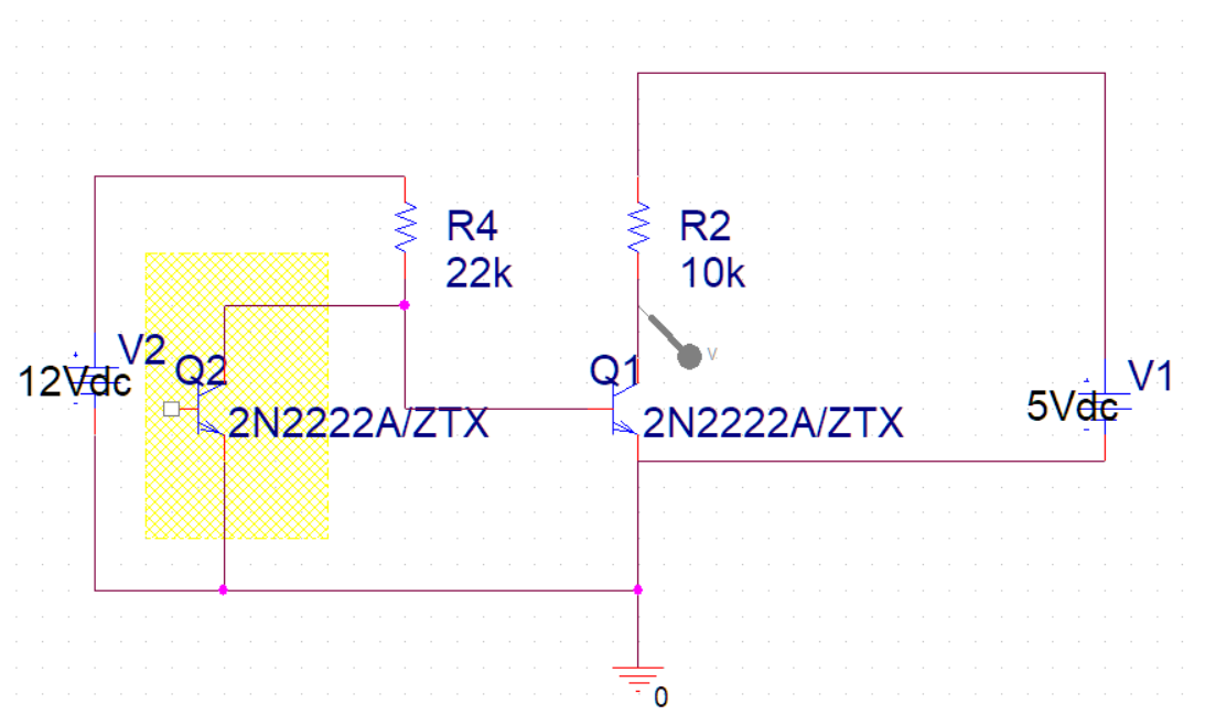
    // I have a 22k pull-up resistor connected to +5V since most fan spec
    // claims they use open-collector setup.
    attachInterrupt(digitalPinToInterrupt(PinTachometer), tachometer_isr, FALLING);

    /* Setup PWM Output
     *
     * Sanyo Denki fans use 25 kHz signal to do PWM
     * whereas Arduino Nano by default uses 490/980 Hz depending on which pin.
     *
     * Use Phase Correct PWM
     * since on Arduino Nano Fast PWM doesn't allow 0% PWM
     * without some hacking: need to turn off PWM to do that.
     * It's possible but just more work.
     *
     * Here we use Timer2 since Timer0 is used for clock for several internal
     * library functions while Timer1 is used for the Servo library.
     */
    // Override OC2A to Phase Correct PWM Mode
    TCCR2A = TCCR2A__;
    // No scaling, Arduino is 16M
    // Phase Correct, OCRA as TOP s.t. output is 25K.
    TCCR2B = TCCR2B__;
    OCR2A = OCR2A__;
    OCR2B = DEFAULT_PWM_DUTY;  // initial PWM set at around 25% duty
}

void loop() {
    static const unsigned clock_period = 72;
    static unsigned clock = 0;

    if (0 == clock) {
        noInterrupts();
        const unsigned long fes = falling_edges;
        falling_edges = 0;
        interrupts();
        // `delay()` is in milliseconds, 2 falling edges per rotation
        const unsigned long rpm = (fes * 30000ul) / ((unsigned long)clock_period * (unsigned long)DelayTime);
        // `tm1637` is, as the name indicates, TM1637 7-segment display.
        // I got a 4-digit one so typical usage range should be covered.
        // library used is [avishorp](https://github.com/avishorp/TM1637)
        // its initializing code are omitted for brevity
        tm1637.showNumberDec((int)rpm, true);
    }

    clock = (clock < clock_period - 1) ? clock + 1 : 0;
    delay(DelayTime);
}

I believe that Arduino Nano should be able to handle interrupt orders of magnitude higher than required serving as tachometer, and besides some fans do always report as expected, so I'm unable to tell if there's some catch in my code.

I'm suspecting that maybe those fans with erratic readings are those of which internal open collector circuits cannot source enough current to make stable output and/or there's some sort of debounce required, but I'm not sure how to implement circuit to help mitigating the issue.

A bit of searching gave me this:
https://www.intel.com/content/dam/support/us/en/documents/intel-nuc/intel-4wire-pwm-fans-specs.pdf

The open collector output doesnt have an internal pull-up. The Pin SINKS current. The INPUT_PULLUP may be a bit too weak to cope with circuit capacitance, so I'd suggest you use an external pull up of around 1k.
Debounce should not be necessary

1 Like

You should not access an interrupt variable, outside the ISR, without turning the interrupt off.

The Pin SINKS current.

Sorry I chose the wrong phrasing. I do know that conceptually the tachometer pin works by turning the BJT (which has emitter connected to GND) on/off to create square wave, thus with open collector & pull up it actually sinks current. Still, thx for correcting me!

A bit of searching gave me this:

I didn't read this Intel doc so thx for the findings! Intel recommends pull up to 12v, whereas I originally connected pull up to only 5v. I tried the following experiment with the following schematic:
(The grey probe is where Arduino ISR pin attached to, while yellow part is internal to the fan)

Original (schematic A):


This above is my original setup, and has encountered several problems as described in original post.

This schematic B below is my modified setup with the Intel doc, trying pull-up to 12v instead of 5v, and added a 2n2222a to change to 5v signal.


The situation has indeed improved: using B, one of the models which only reports correct readings with duty either 0% or 100% in schematic A now reports as expected with all duty. Nice!
However there's still a fan model, that reports all over the place (ranging from several hundred to nearly 10k) in schematic A, continuing to act weirdly in schematic B.

Yes the only place I access the volatile counter outside of ISR is in these lines

You dont need to pull up to 12V to get a 5V signal.
However as I said the 22k is probably much too large.
Change your first circuit to use a 1k or 2k2 resistor and I bet it works fine.

The high impedance could be allowing interference from the adjacent PWM line.

Again for your patience and kindness!

I had tried schematic A (tachometer open-collector pull-up to 5v) with 1k pull-up resistor but the one particular fan (let's call it WF for weird fan) still goes haywire reporting nonsense, thus I tried schematic B. Most of the fans are fine with B while the only misbehaving remained is again WF so I settled with schematic B that day.

Now that you've mentioned it again, I checked again schematic A with different pull-up resistor. This time I observed more closely and discovered that with 1000 ohm, though WF readings are still jumping around for most of the duty ratios, as long as the resulting RPM is below like 1700 or so then it's indeed reporting correctly (on this specific model, around 35% duty). I went ahead and go even lower on the pull-up resistor and tried 220 ohm, and this time WF with schematic A i.e. 5v pull-up reports correctly up to around 2500 RPM (correspondingly 61% duty), which is nice. Though this fan is rated at 3300 RPM and anything above 61% duty the readings would still go haywire and starts jumping around by several thousands.

An interesting thing I observed is that as long as I physically touch the 220 ohm pull up resistor with my fingers, WF reports correctly for around 1% more duty (my code specifies granularity of 1/80 so it's around 1.25% to be specific), so I guess the issue does involve some interference here.

I tried also even lower pull up resistor, like 147 ohm (100 + 47), with schematic A. The variation of the readings remain small up to 79% duty (around 3200). But unfortunately the readings seemed to start drifting away from the truth even when the variation of the readings remain small: if I were to again physically touch the two pull up resistors (which are in serial), the readings are down by 200 to 3000, which I believe is a more accurate measurement of RPM based on the sound profile of the fan and the fact its max rated RPM is 3300 and there's still like 20% duty from 100%.

I can't go lower though: with 100 ohm schematic A the fan WF itself starts to ignore some lower duty signals i.e. if I were to set the duty ratio too low then the fan just ignores the signal and would not spin any slower.

Currently I settled with 220 ohm pull up schematic A; the WF model respects duty input and reports tachometer mostly correctly up to 61% duty or 2500 RPM, and all other models are working as expected.

1 Like

Just in case anyone came across this post in the future:
I mistakenly set OCR2A to 79 instead of the correct value 40, which makes the pwm for the fan around 16*10^6 / (2 * 8 * 79) which is around 12658 instead of the required 25000.

That is, the correct register settings should've been as such: (phase correct, 25k pwm, TIMER2 on Arduino Nano with Atmega328p)

void setup() {
    TCCR2A = _BV(COM2B1) | _BV(WGM20);
    TCCR2B = _BV(CS21) | _BV(WGM22);
    OCR2A = 40;
}

This change seem not be related to the tachometer problem described though; the WF fan's tachometer still misbehaves when above certain duty cycle. Thanks to this guy at electronics stack exchange community to point this out.

This topic was automatically closed 180 days after the last reply. New replies are no longer allowed.