Hello,
I am very new in electronics so I am asking to help me with this. Sorry for my poor English
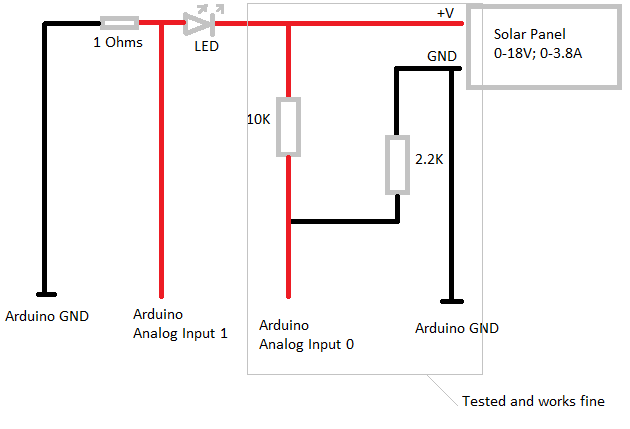
I attached my solar panel multimeter scheme. I need that arduino reads Voltage and Current at the same time. I have read a lot of posts in this forum, but apparently I am too stupid to do it by myself. My arduino reads voltage correctly, but I don't know how to measure the Current.
I made something like this: http://www.arduino.cc/cgi-bin/yabb2/YaBB.pl?num=1205745528/0
and blew up some LED's. So I need something else. Can someone please correct my scheme so that Arduino Analog Input 1 reads Current correctly? Can I use something else instead of LED? I just don't want to blow up my Arduino Duemilanove.
You can only measure current going through a load, you have no load on your solar cell apart from the 1R (ohm) resistor. In effect you are shorting out the cell. If you turned the LED the other way round you would light it up but would also blow it up because you have nothing to limit the current through the LED.
In place of the LED put the circuit you want to power. Then what you have will measure the current through it.
Thank you for your replay Grumpy_Mike!
I want to load 12V car battery with this solar panel and I want to measure how much Current is going in to the car battery.
With 1R sensing resistor you can monitor currents safely up to 5A, any more than that and you might damage the arduino input pins. If that is the case then follow the sensing resistor with a potential divider like you did for the voltage or add a series resistor of about 300R and put a 5.1V zenner diode across the analogue input 1.
Grumpy_Mike:
That's what the 10K and 2K2 resistors are doing.
In the picture, analog input 1 could go as high as 18v if the led was shorted and 18amps went across the 1ohm resistor. At best the led could only drop 2v leaving a possible of 16v on A1.
I hope I didn't jump the gun, but my reasoning is if your solar cell does not have anything to prevent the current from going above 3.8 amps "in the event of a short" then you could have a problem.
If the current never goes above 3.8 amps then you will never have more than 3.8V across the resistor.
In your new picture the battery is shown backward and the A1 input needs to be between the 1 ohm resistor and the battery.
Sorry for that. I am just getting into this.
My solar panel will not go above 3.8 amps, it should not because max current is 3.5A
Is it all correct in this picture? Sorry, I just want to be sure.
So Analog Input1 volts is equal to the amps from the solar panel, right?
Big thank you for your help!
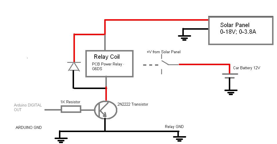
Hello, I have another stupid (I think so) question about relay, sorry about that. I want to make easy charge controller to my solar panel, so I am thinking to add relay as a switch. When battery voltage gets to 14V - arduino give a signal to turn solar panel off, and when it gets under 11.8V - turn solar panel again on.
I made a little schematic of my circuit. I just want to be sure that I have chosen right relay and transistor and that my circuit is correct.
Thank you again for all your answers.
P.S. Datasheet for relay https://www1.elfa.se/data1/wwwroot/assets/datasheets/hrG6DS_data_e.pdf
Datasheet for transistor https://www1.elfa.se/data1/wwwroot/assets/datasheets/zc610022_e.pdf