Rechargeable Battery - 5v needs 350mA

Hey Guys.

I am looking for a rechargeable battery. I am hoping the battery can be charged by USB and has a controller ? built in. Something that will stop the battery from charging, either on the battery or in the usb charging cable itself. More preferably in the battery itself so any standard USB cable will be able to charge the battery.

I am hoping the battery will be able to power my project for a minimum of 3 - 5 hours (depending on the charge time of the battery).

Any terminology to help guide me in the direction, or even products and links would be great.

Thanks for your time.

"power bank" ?

This seems to fit you rather limited description requirement.

[https://www.google.com/search?q=power+bank&tbm=isch]Take your pick.[/url]

USB charge, USB output, charge controller built in, output voltage control built in, overcurrent (short circuit) protection built in. I've used a pair of 16800 mAh power banks to power a project with 120 WS2812B LEDs + DF Player, lasts 8-10 hours.

350 mA * 5 hours * 1.5 (you never get 100%) = 2600 mAh. That's pretty small for a power bank.

Ok.

My project will be running off an Arduino Nano.

I will also be using a bluetooth module HC-05.
30mA

The project will have 5 RGB LEDS running all the time, yet 3 will always be red and 1 will always be green. There may be a yellow and blue with 3 red lit.

20mA x 3 - red = 60mA
40mA x 2 - dual color = 80mA or 60mA x 2 = 120mA

= 140 mA ~~ 180mA

There will be 5 motion sensors HC-SR04, but one "sensing" at a time.
15mA

For my basic understanding, I will be running, at a single time

185mA ~~ 225mA

correct so far?

I am trying to power sufficiently for roughly 5 hours, with an installed, USB rechargeable battery.

I have been looking at 2 3.7v 1AH batteries to power my project.

https://www.digikey.com/product-detail/en/sparkfun-electronics/PRT-13813/1568-1492-ND/6605198

Would I be able to charge the batteries using a single control board?

I am getting hung up on this aspect of the project. I do not want to have to replace a 9v battery every hour or so, but I don't want to have issues with not sufficiently providing constant current to my components.

RECAP
Arduino nano w/ bluetooth module req. 30mA
5 RGB LEDS (20x5 or 60x2 + 20x3) req. 100mA ~~ 180mA
Motion Sensor req. 15mA

2 3.7 rechargeable 1AH batteries

Any corrections or someone with a better understanding able to provide me with guidance on this issue?

b3y0nd:
I will also be using a bluetooth module HC-05.
30mA

Sounds high but better too high than too low for estimtation.

The project will have 5 RGB LEDS running all the time, yet 3 will always be red and 1 will always be green. There may be a yellow and blue with 3 red lit.

20mA x 3 - red = 60mA
40mA x 2 - dual color = 80mA or 60mA x 2 = 120mA

5 mA is usually more than enough; maybe even 1 mA as it's just an indicator LED. Lots of savings possible here!
Shouldn't be more than 35 mA.

There will be 5 motion sensors HC-SR04, but one "sensing" at a time.
15mA

Datasheet says 15 mA indeed - not sure if that's constant or only while sensing. I guess the latter. You're not sensing all the time, so that's going to be a lot less. Maybe 5 mA average.

I'm at ~70 mA now.

I have been looking at 2 3.7v 1AH batteries to power my project.

One will do just fine. 3.3V Arduino, 3.3V HC-SR04. One less battery, and you will get the same if not better battery life out of it (!) thanks to the lower voltage and no need for regulating the voltage to your devices, as they'll work just fine on the slightly higher voltage of the battery.

There are modules out there that allow for USB charging and using the battery for power at the same time.

Thanks Shannon.

So, you are saying that a single 3.7V battery would be able to hand the operation of my project?

As you seem to be monitoring this post...

I have 5 RGB leds x 3 leads - 15 output pins

I have 5 motion sensors x 2 lead (trigger echo) - 10 output pins

I need 25 output pins.

However, I have seen people use the Trigger and Echo lead on the same pin.

Do you have any idea the cost / person required / or process for me to complete a personal board for this project? One that incorporates the Blue tooth module?

I will be wanting to update the program on the board, but will have to continually disconnect the Blue tooth module to do this with my current situation. If I stay with my current circuit, is it feasible to add 2 switches, allowing the disconnecting of Bluetooth Module from the TX RX?

Thanks for your guidance.

b3y0nd:
Thanks Shannon.

That's just some kind of grade related to the number of posts :slight_smile:

So, you are saying that a single 3.7V battery would be able to hand the operation of my project?

Absolutely. You're used to 5V so probably focussed on "it must be 5V" but most components work over a range of voltages. ATmega processors work at 1.8-5.5V, it's just that at 3.7V you have to reduce the clock speed to no more than about 12 MHz. The internal 8 MHz oscillator works wonders for this, especially if you don't are too much about very precise timing.

I have 5 RGB leds x 3 leads - 15 output pins

I have 5 motion sensors x 2 lead (trigger echo) - 10 output pins

I need 25 output pins.

However, I have seen people use the Trigger and Echo lead on the same pin.

Easiest is a port extender like the PCF8574/MCP23009 (8 I/O), PCF8575 or MCP23017 (both 16 I/O), controlled over I2C. The PCF chips are cheaper but can only sink current, a HIGH output is by pull-up resistor. Still works great for LEDs, or the trig pin.
Echo pin must go directly to an Arduino pin, or you will never be able to get the timing right.

Do you have any idea the cost / person required / or process for me to complete a personal board for this project? One that incorporates the Blue tooth module?

You want someone to design/build a complete PCB for you, for this project? I can do this. Just need detailed specifications. Sounds like a petty straightforward build to me.

I will be wanting to update the program on the board, but will have to continually disconnect the Blue tooth module to do this with my current situation. If I stay with my current circuit, is it feasible to add 2 switches, allowing the disconnecting of Bluetooth Module from the TX RX?

That complicates the matter a bit. Most Bluetooth modules need 3.3V; if you have one on breakout board (with some pins sticking out at one end) it'll have a regulator on board. You still need to worry about the TX/RX levels.

One way to update the board without disconnecting the BT module is to add 1k resistors in the TX/RX lines, that way the update Serial basically overrides the BT one. Another way is update using the ISP interface instead of Serial. Yet another way is to connect the BT module to two regular I/O pins and use SoftwareSerial.

If you want a fully custom board you may even go for a different processor, e.g. the ATmega324PB, or for more memory the ATmega644 and ATmega1284. Those have 32 I/O and two hardware Serial interfaces.

The reason for a personal board would be to eliminate clutter, and have resistors built in specifically for the LED i/o pins...?

I am limited on space for the micro controller and the battery, as everything needs to fit in the base unit or connecting "rod" to each base unit.

Thus, I was trying to place the arduino nano and bluetooth module in the connecting rod as they are thin, and somehow incorporate the battery into one of the base units, which also house the motion sensors. There of course will also be a rocker switch of some sort to power the unit on and off.

I was sketching the project placing a 9V battery in the connecting rod, but the thickness of the 9v was 3X 4X thicker than the MCboard / BlueTM. Thus I was seeking another power source. Looking into something rechargeable and longer life, just incase my kid decides to practice for over 4 hours without charging.

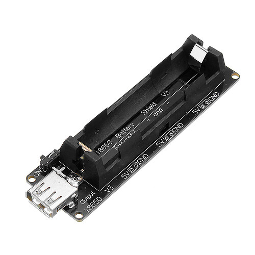
I started looking into 6V or 9V rechargeable, but could not understand how to "make" my own regulated charger for these batteries. The "simplest" form I found was that charging board referenced above.

I would not mind having a standalone charger that connects to the installed battery through a screw open port and disconnect the battery from the circuit to the charger but again, I did not fully grasp 1) the charging of the battery process being regulated 2) having another component instead of just being able to plug a USB in for charging 3) the nano being able to properly function with said components.

As far as the personal board...
what would you need to "design" the board?
number of i/o pins?
components?
bluetooth?

How many produced to make it realistic?

I figure same board for the Bluetooth module and the MC itself would eliminate "space" as the components would be on the same board. I have seen the NANO sold with bluetooth built into the board, yet again, if I were to purchase that, it doesn't provide the needed I/O pins, and did not want to eliminate the BTM just to add ICU's to be able to bit switch and control the LEDS. eliminating a component to add another.

Thanks wvmarle

I found this: Polymer Li-Ion Cell: 3.7V 5000 mAh (7250115-2C, 18.5Wh, 10A rate) - UN38.3 Passed at: Polymer Li-Ion Cell: 3.7V 5000 mAh (7250115-2C, 18.5Wh, 10.0A rate) They also have chargers for these batteries. This response is to help you get started in solving your problem, not solve it for you.
Good Luck & Have Fun!
Gil

Thank for the post.

This was hopefully to find someone with knowledge, or point me to a youtube video that better describes the block I am hitting in this process.

I.E. something that describes a battery controller for charging and what they specifically control, the voltage input and amp input into the battery during charging.

This project is for learning reasons and personal enjoyment.

Answers are great, reasoning is better.

b3y0nd:
The reason for a personal board would be to eliminate clutter, and have resistors built in specifically for the LED i/o pins...?

You can make stuff a lot smaller often, by leaving out parts you don't need, placing it closer together, or even using both sides of a PCB.

You're talking about "motion sensors" but the HC-SR04 is of course just a distance sensor. For that, there are much smaller options (like the VL53L0X, which is a few mm square). The HC-SR04 is pretty big. A more true to word motion sensor is the RCWL-0516 module, sensing motion a few meters away and in all directions. Moving your arm is enough already (now imagine a group of 6 dancers standing around 12 of those sensors and no motion allowed for 30 seconds - that was interesting :-)).

There are dedicated charger ICs for LiPo batteries. A fixed resistor sets the charge current (based on the battery capacity), the IC takes care of current control and charge control - regulating current, cutting it off when the battery is full, etc. No doubt the device in #2 has one such chips, probably on the back of the PCB. How they do that exactly I don't know, that's for the charger specialists.

As far as the personal board...
what would you need to "design" the board?
number of i/o pins?
components?
bluetooth?

For starters: circuit diagram (seems you don't have that yet), or a complete list of components and what they're supposed to do.
LEDs mounted on the board, or wired to the board, for example. What connectors in that case is another parameter, in the first case the type/size of the LEDs.
Allowed size/shape of the board.
Mounting holes/slot and location of them.
That kind of things. Things like number of I/O pins follows from that.

How many produced to make it realistic?

Depends on what you want... Lots of projects are one-off. You normally start with just one or two boards, to make sure everything is fine: circuit correct, traces correct, physical fit OK, no overheating, etc.

Such a Nano w/bluetooth can be a very good basis for a one off board (saves cost in components and effort), mount that on top of another board which has the rest of the components, which will likely include a port extender in that case.
As far as the board...

I am looking to handle:

5 RGB LEDS middle of arms - 3 leads x 5 = 15

5 motion sensors - in the base of legs - 2 leads x 5 = 10

on/off switch

bluetooth communication

microcontroller programmable

and if possible the battery able to charge + power everything from the same software upload port