I am using an Arduino Mega and an LCD to measure, log and display the current through a typical AC 120V 60Hz wire. I'm not concerned with the logging or display I can handle that.
I am using a non invasive CSLA2CD Honeywell current sensor:
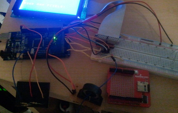
The sensor:
Currently set up using the 5V and GND from the Arduino with the output pin directly to A0.
At zero current it reads a nice and happy 512 or half of the 5V (it's more like 4.89V according to the multimeter so half is actually slightly less than 2.5V)
Using a 1V current source and a 1Ohm 10W resistor I put approximately 1 Amp through the loop and depending on the direction of the current it will happily jump to 517 or 507.
The problems:
Resolution, I need no where near 72A. I want a maximum of approximately 15A.
I don't really NEED to measure current in either direction for typical 120V AC wall current as long as I have it wired correctly right?
Amplifying the output from the current sensor and keeping 0 current at 2.5V or at least half of AREF.
Noise, perhaps I need a LPF, adding gain seems to significantly increase noise in the reading.
What I need:
Resolution of approximate a tenth of an Amp from 0 - 15A. More would be nice, but I'd be content with that.
Desired solutions:
The solution I'd like to use is with an op amp or two to give a gain of approximately 5 to the output and keep it centered at 2.5V, I'm considering a circuit similar to the one outlined for the inverted pendulum potentiometer by Microchip: http://ww1.microchip.com/downloads/en/AppNotes/00964A.pdf
See top diagram on Figure 8.
Alternative solutions/thoughts:
I've currently been playing with the internal AREF as well which when I used the internal 1.1V or 2.6V produced unacceptable amounts of noise and variations which changed drastically from input voltage (plugging in another USB device in to the same computer was enough to through it off by 20 points) however using an EXTERNAL AREF with a simple voltage divider from the Arduinos 5V produced much better results, I'm not sure it's quite what I want, besides I still need to shift it.
Solutions I don't want:
Get another sensor, the CSLH3A45 is only 45A, however it is an interesting package I'd rather not mess with.
The little black board is the voltage divider for Aref, I tried to keep it away from all of the interesting things to the right. I'm using .5K on the 5V side and 1K on the GND side giving me ~ 2/3 * 5V = 3.33V for an AREF or about a 50% gain on our signal (512 * 1.5 = 768, I'm hovering around 778-779 with no current which is within tolerance from resistors).
And try your best not to cringe at the LCD connections, I have a PCB coming to clean that up nicely which I spent quite a bit of time on.
edit:
Also interesting, oversampling for more resolution...
You will want a single-supply op-amp that can work close to the power supply rails. eg: TI TLV2772. Use one amplifier to make a virtual ground at 2.5V, then build an inverting amplifier out of the other to yield the gain you need.
That's what I was thinking, getting the right voltages for the virtual ground looked to be the interesting part. Thanks for the recommendation for the Op Amp, mouser was what like 11,000? I get lost trying to choose one that will work.
getting the right voltages for the virtual ground looked to be the interesting part.
No that's simple. Just have two 1K resistors in series going to +5 and ground. The junction is the 2.5V virtual ground. Just put a capacitor across the lower one 0.1uF to 4u7 to make it a low impedance and the job is a good one.
However note that you can't always amplify the signals from these current sensors successfully because when a signal is low it is the same sort of size as the noise and the noise gets amplified as much as the wanted signal. Look at signal to noise ratio.
I think I would use a trimmer rather than fixed resistors to establish the virtual ground level. This gives you some adjustability which you might need if the fixed resistors are not exactly the same value.
If you use the voltage divider and feed that into the non-inverting input of a unity gain voltage follower, the output is your virtual ground and is of quite low impedance. It will source or sink 30 ma or more.
I think I'm going to try to do some oversampling as well like listed in that Atmel article to hopefully try and limit some of the noise, but here are the specs from Honeywell:
The CSLA2CD is the smallest of this series. Since it is purely AC, I should be able to put the capacitor in series to increase accuracy as well.
So is this close to what I need?
Ignore part numbers and assume that pot on the left is the sensor.
The way I read this is that if the current being monitored is AC, the sensor output is also AC. If this is the case, it will make your measurement circuitry a bit more complicated.
Theoretically you can rectify the signal, but since it is small, the forward voltage drop of a diode will come into play. A better approach would be a peak detector and sample/hold circuit.
Yes, I think you're right, perhaps I need to step back and do some testing with a signal generator and an oscope to get a better picture of what I'm trying to read... which I don't have access to until probably Wednesday.
http://openenergymonitor.org/emon/node/59
Well this guy did something similar and also used an AC-AC adapter to get the voltage. With the voltage you can take a ton of samples (it's only 60Hz...) and multiply instantaneous current with instantaneous voltage to get an instantaneous power and do some math to integrate and estimate a fairly accurate average power. I think I'm going to attempt something similar. He has his sketches posted as well. Those current loops should work fine and I think I can get away without an amplifier if I just route the wire around a few times, a solid 12 ga copper wire has no problems wrapping around 5-6 times if you are careful with your bends.