I have 8 channel 5vd relay (songle srd-05vdc-sl-c 8) with active low and its first and second relay are connected to a solenoid valve (airtac solenoid valve 4v230c-08 , 24vdc 4.8W, and it has two solenoid). I have used an external PSU with 24vdc 12,5A and step down XI405 (to convert to 5vdc). the first solenoid is connected to first relay and so on. I have coded the program for only turn on the first solenoid and next turn on second solenoid, turn off first solenoid, like a running blinking LED. The problem is that when the lod isnt connected to the PSU, everything is fine, the first relay but when they are connected to the PSU then the relay won't switch off, for example after the first solenoid turn on, then delay 2 sec and then turn off, but the relay won't turn off and my second relay won't turn on. Are the relays faulty? or am i missing something?
Any help or advice you could provide would be much appreciated.
Please confirm that you have measured the various voltages while your code is running and the voltages are correct and change very little wile operating.
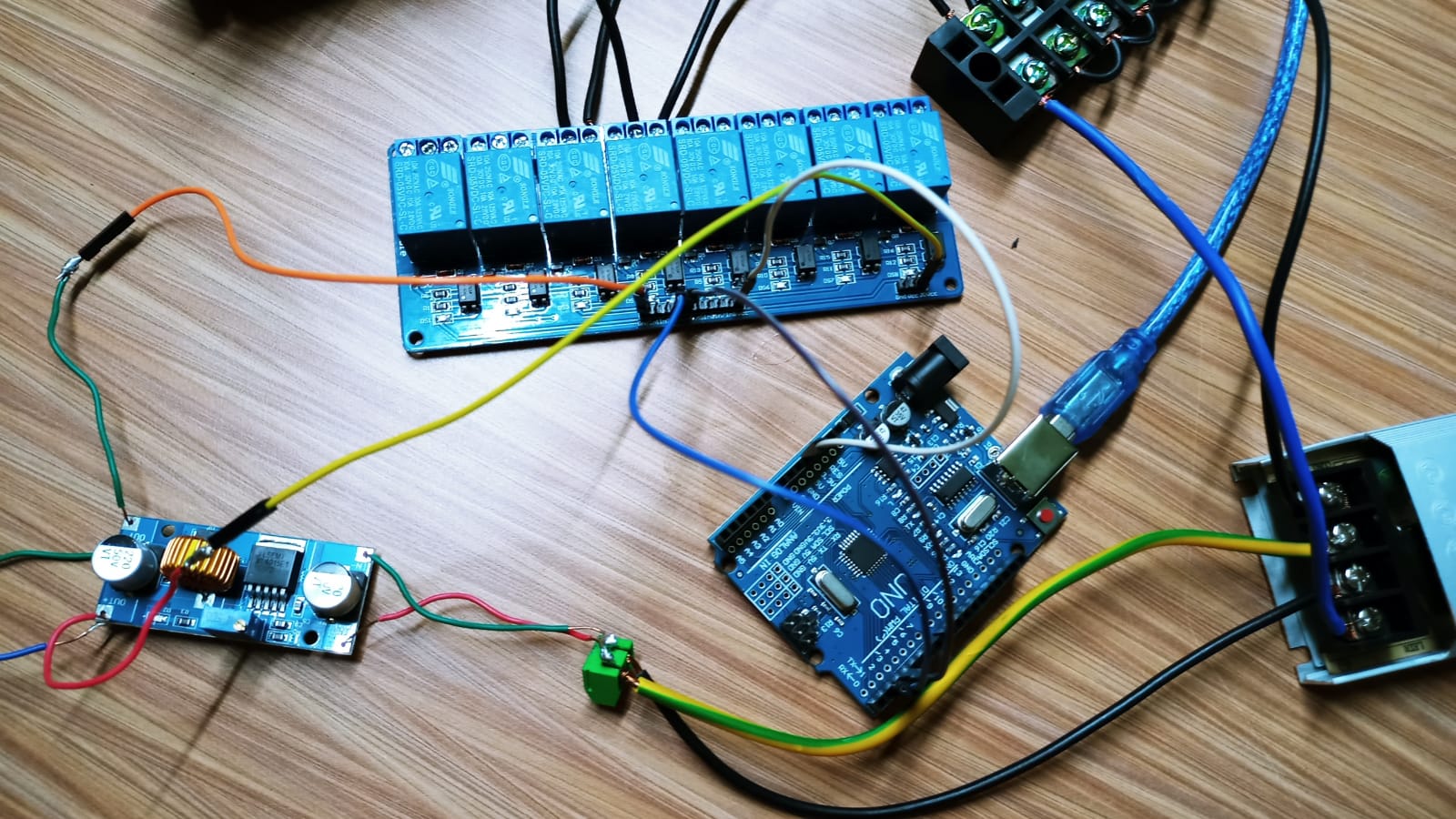
I have separated the power like you schematic (4 channel relay board), one from usb (from my laptop) for arduino and one for the relay board from psu. As in my schematic, the solenoid have their own power supply that is 24vdc. When i try to run my code the solenoid work for a while just as intenden in the code, but then the first relay keep turning on while the second relay turn on and off very fast.
i have measured the voltage, everything is fined except the voltage output from the arduino pin. It shows 1.8-2.8v eventhough the pin is active. I have read that the output voltage from pin when the arduino is connected to usb is 5v. Am i missing something?
That shows the pin is actively changing from low to high because your program is doing something with that pin. Perhaps your program should not be changing that pin quite so rapidly.
its zero and i have measured the voltage from vcc board that is connected to 5v arduino (when arduino plug into usb laptop), it shows zero too, eventhoung the arduino led is on
PLEASE get out pen(cil) and paper......
Reverse engineer your project.
Draw a copy of your circuit, a picture of a hand drawn circuit in jpg, png?
Hand drawn and photographed is perfectly acceptable.
Please include ALL hardware, power supplies, component names and pin labels.
light box power supply (from local electronic shop) 300W 24V
Input: 200-240V-50-60Hz
Output: 24V 12,5 A
Step down 5A XL4015 Module
Voltage and Current Input= 4-38V & 4A
Volt and Current Output = 1.25-36V & max. 5A
Power Output: max. 75W
Consumtion: 18mA without load
terminal block
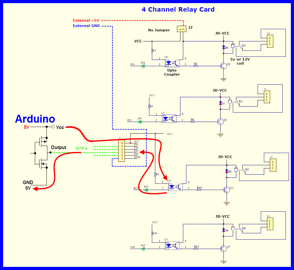
Here is the hand drawn circuit and the photos:
How do you plan to power that relay module, if you connect +5 V but not GND? And as already being said, depending on the power need (both continuous and peak), it might be better to power the relay module from a dedicated 5 V source and not the Arduino.
Edit:
From the datasheet, and notice the marked numbers
Hi,
Include in your code the "Blink without delay" example.
This will make the on board LED flash when your code is running.
Its termed a "heartbeat LED".
If when you problem occurs and the LED ceases to flash, then it means your code has locked up.
Probably due to noise spikes on your power supplies form the valve solenoids.
If it continues to flash then a wiring or software problem.
Hi,
I have found the problem and it just as you said, its the noise spikes from my solenoids. I have put the a diode accros the solenoid and now it works fine