If you have just a relay module, without flyback diode the arduino pin most certainly will stop working. Furthermore, if your relay coil is not rated for 5V then you can use optocouplers as additional protection and means to switch higher voltage.
Ok, regardless, I can see it does not have a flyback diode. Even though the coil will activate at 5V then whet it closes there will be a high voltage spike with reversed current flow. The flyback diode should fix that. Optocoupler should help even more, as the arduino output can provide only 20mA so the coil might energize slowly. Adding optocoupler could help with that. The faster the relay switches, the less likely it is to weld it's contacts.
I'm not really fluent with transistors. But it looks like it would work. Just make sure current going through output transistor is not higher than in specification. I would use single logic level MOSFET with buildin flyback diode. Also test the circuit before connecting it to amplifier.
Yes, except that the 1k resistors wold be better as 10k or 47k and the IRF530 is the wrong device but will probably work in this circuit.
Clearly!
There is no such thing. Can you cite one?
Actually, there would not be when switching an Arduino pin set to OUTPUT.
Nonsense!
No it won't. While the Arduino actually has an upper limit of 40 mA nevertheless the relay will probably not actuate at all.
No it won't!
Perhaps.
A relay module as readily available on Aliexpress, eBay and (faster at) many hobby shops, contains a transistor which is necessary to switch the relay current of generally about 90 mA for a 5 V relay.
Rubbish! An optocoupler has its purposes, but it is the transistor which switches a greater current and if necessary voltage.
The OP specified a 5 V relay.
He is - appropriately - talking about a high-side switch instead of the relay.
I would be a bit sharper providing replies if Firefox did not crash so frequently!
I might use wrong terminology as I know the part names mostly in Polish.
Actually, there would not be when switching an Arduino pin set to OUTPUT
I did an "experiment" with Arduino Nano. I accidentally connected 12V to one of the arduino pin that was set as an output. Part of the ucontroller lightup like a sun. So high voltage spike from relay coil surely would damage the output.
No it won't. While the Arduino actually has an upper limit of 40 mA nevertheless the relay will probably not actuate at all.
That was my point.
Rubbish! An optocoupler has its purposes, but it is the transistor which switches a greater current and if necessary voltage.
Indeed, but optocoupler has transistor in it. But I agree it is no the main purpose.
A relay module as readily available on Aliexpress, eBay and (faster at) many hobby shops, contains a transistor which is necessary to switch the relay current of generally about 90 mA for a 5 V relay
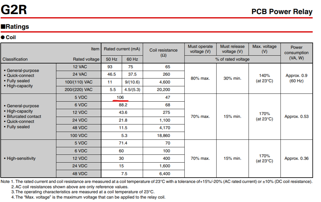
Datasheet for OPs relay has no mention of integrated transistor. It also states that for 5V you need around 100 mA of current. That's why I siad that optocoupler might be helpful (but not ideal)
That's not a flyback/freewheel diode. It's the body diode that virtually every MOSFET has, but it has a different function and cannot (physically, electrically & theoretically) used as a flyback diode in the kind of circuit you're thinking of.
It's even easier to use any old npn transistor or small signal mosfet to switch those lousy 100mA the relay needs. Why drag optocouplers into it?
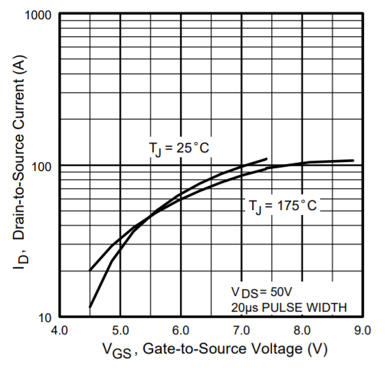
It wouldn't necessarily have to be a big MOSFET since you'd pick one with a low RDSon so it would dissipate virtually no power. If you want to use a high-side switch (i.e. you're going to switch the V+ of the amp, not it's GND), you need a P-channel MOSFET and a little circuit with a second MOSFET or NPN and a couple or resistors to drive the P-channel FET, as you can't turn it on directly from a 5V Arduino if it has to switch 24V.
To select a proper MOSFET, for the P-channel one select one with low RDSon and with a continuous permissible drain current that exceeds your needs; I'd say upwards of 15A; otherwise it's not very critical. For the auxiliary MOSFET or NPN, it's not very critical as long as it will survive 24V, which most transistors (MOSFET or otherwise) will.
A relay isn't a very silly idea if a simple solution is desired. I'm not so sure if the GR2-1 will live very long if it really needs to switch 9.5A. I don't know off the top of my head what the contacts of this relay are rated for, but I doubt it's 10A DC.
You're either close to, or well above the contact ratings depending on what exact model you have.
You might be OK. The relay might also self-destruct within a short period of time. Who's to say?
The good news is that this particular product line is pretty sturdy. They've been around for decades and remain popular - for good reason.
So you connected a 12 V power supply to the Arduino pin? Do you understand that is different from a relay?
To the extent that the microcontroller can safely drive the relay coil, when set to an OUTPUT, it switches either to ground or to 5 V. When it switches, whatever current the relay was passing from one supply line, is simply transferred to the other supply line. So there is no "voltage spike". Truthfully, people - even engineers - seem to become very confused about how inductors work.
The optocoupler has negligible gain. Common specifications give gains (CTR) in the order of 0.5 to at most 6. And that at much lower currents.
It depends. You referred to a "relay module".
Even with a gain of three (which is an edge case), an optocoupler is not appropriate for controlling a relay as it is not rated for 100 mA. Maybe if you use 24 V and a 24 V relay ...
But with the transistor (or FET) and "kickback" diode, there is no problem, so
it is not going to be an issue.
You do not switch the ground of an audio amplifier. And an IRF540 is not a logic-level FET.
Perhaps you should not be offering advice until you understand quite a bit more about all these things? Do a lot more reading on the forums here as it is often explained.
I sort of assumed (but it's not clear) that he intended that schematic for driving the relay. But it seems, given the amp-1&2 connections he intends it to switch the amp. I agree with you - it's a pretty insane way to switch that amp, and it certainly is never going to work with that MOSFET. It's a 'solution' that's going to spawn a new series of problems.