This is my first post here, so sorry if I am messing up something. I tried to find a similar post but could not find it. Also, I am new in the Arduino world and a newbie with eletronics.
So, this is my problem: I have a 12V single relay with optocoupler (at least it looks like an optocoupler) that I want to connect an external power supply to separate a solenoid valve, that I am trying to control, from the Arduino's circuit. But I am not sure how to connect the external power supply, or if I can at all.
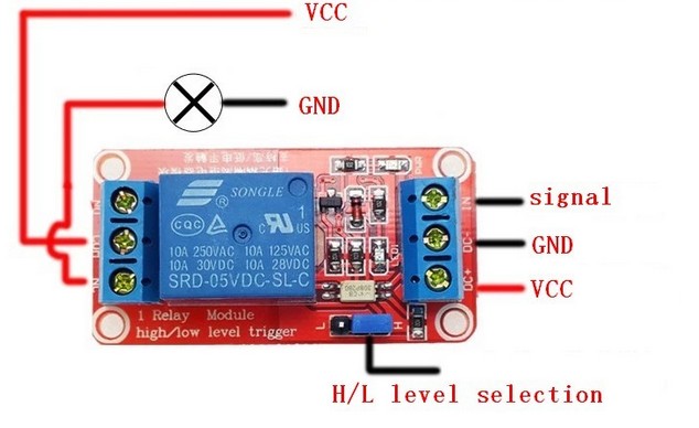
My relay looks like this one but 12V:
I have seen in other relays something like JVcc (or something like that) where you are supposed to connect your external power supply to make use of the optocoupler, or you can leave the jumper in the pins to use the Arduino as a power source to the relay but without the optocoupler isolation.
Mine has also those 3 pins with jumpers, but they are labelled as H/L (see image). My question is: Can I connect my external power supply to these H/L pins to make you of the optocoupler or this is completely
wrong?
Sorry for the long post and thank you guys in advance,
The relay pin "signal" is connected to the Arduino pin your program controls to operate the relay. The program may set the pin LOW to turn on the relay, or it may set the pin "HIGH" to turn on the relay. The H/L jumper is set to match the way your program sets the pin.
The VCC on the right side is where you power the relay, 12 volts in your case. All the grounds, 12 volt power and Arduino must all be connected together.
The left side of the relay is for whatever you are controlling, but you already know that.
Paul_KD7HB:
Hi, Rafael.
Welcome to the Arduino forum.
The relay pin "signal" is connected to the Arduino pin your program controls to operate the relay. The program may set the pin LOW to turn on the relay, or it may set the pin "HIGH" to turn on the relay. The H/L jumper is set to match the way your program sets the pin.
The VCC on the right side is where you power the relay, 12 volts in your case. All the grounds, 12 volt power and Arduino must all be connected together.
The left side of the relay is for whatever you are controlling, but you already know that.
Paul
Hey, Paul.
Thank for the reply!
Does that mean I cannot connect an external power supply to this relay to make use of the Optocoupler (is that white 'thingy' an optocoupler?)? If not, does the arduino still gets isolated from the rest of the circuit?
It has a JD-VCC, VCC and GND pins to connect an external power supply. Will mine work the same with the H/L pins or it is something completely different?
The black, square things are the opto-couplers. One per relay.
Your external 12 volt supply connects to the VOC pin on the 4-pin header. The in1 and in2 pins connect to your Arduino, just as I wrote before. The 3-pin header on the left selects how your program turns on the relay. High active or LOW active.
And all grounds connected together to make complete circuits.
Paul_KD7HB:
The black, square things are the opto-couplers. One per relay.
Your external 12 volt supply connects to the VOC pin on the 4-pin header. The in1 and in2 pins connect to your Arduino, just as I wrote before. The 3-pin header on the left selects how your program turns on the relay. High active or LOW active.
And all grounds connected together to make complete circuits.
Paul
Ok, I think I got it now!
Just two last questions:
Since my Relay (The red one with H/L level selection) does not have inputs for external power supply, will my arduino be isolated from the rest of the circuit?
On the right side, does the signal Voltage needs to be equal to the VCC Voltage? In other words, can I connect a 5V digital pin from the arduino to the Signal input on the relay, while its VCC voltage is 12V?
Sorry for asking so many questions and taking so long to understand, hehe.
Rafael
BOTH RELAYS HAVE INPUT FOR AN EXTERNAL SUPPLY!!!!!!
Paul_KD7HB:
BOTH RELAYS HAVE INPUT FOR AN EXTERNAL SUPPLY!!!!!!
Paul
Ok, I tried and it worked.
But I still don't get it how isolation works in this case. I've seen some sites and diagrams (http://arduino-info.wikispaces.com/ArduinoPower#OI) showing how to achieve isolation and it looks completely different.
I doubt you have a reason to bother using isolation. The modules already have transistors and flyback zeners. By the time you build something worth isolating, you might then have enough knowledge about electronics to know how.
INTP:
I doubt you have a reason to bother using isolation. The modules already have transistors and flyback zeners. By the time you build something worth isolating, you might then have enough knowledge about electronics to know how.
You might be right. I am not really sure if I need to isolate it, since it is only 3 12V solenoid valves. I just heard someone suggesting using an optocoupler but I didn't really asked why.
flokada:
You might be right. I am not really sure if I need to isolate it, since it is only 3 12V solenoid valves. I just heard someone suggesting using an optocoupler but I didn't really asked why.
Anyways, I'll see how it goes without isolation.
Thank you.
Rafael
Goes to prove my point.
The devices, in your case solenoids, are not what is being isolated. They already are.
No, It is not the correct schematic. The octocoupler emitter is bidirectional on his board. And L1, and L2, has been moved to the output of the octocoupler . The center pin of the jumper goes either to the resistor or directly to the emitter. The two outside pins, is positive and negative. Removing the jumper and placing power, +/-, To the center terminal will totally isolate the relay from the microcontroller. Unfortunately the emitters current limit resistor is set up for 12V. It may or may not work correctly. If you're using a 12 V power supply to power the Arduino, or even a 9 V power supply, you may need to go from the power in pin to make it work, with active low signals.
Hey guys, I really appreciate your help! (and sorry for the very late reply, I was kinda busy)
Since I am very newbie in electronics, those schematics are way too confusing for me. I'll try to explain what I am trying to do, so you guys can tell me if something is wrong.
I want to activate the relay (that will active a solenoid valve) using an external 12V power supply and the arduino's 5V from a digital pin, in other words: connecting 12V (from power supply) on the relay VCC, Ground (from power supply) on relay GND and 5V (from Arduino's digital pin) on relay Signal.
Is that correct or I am going to explode something? (I'll leave a 'very nice' schematic that I made, to make things easier to understand).
You could put a 1N4148 diode between the Arduino output pin and the relay signal pin, (cathode (end with stripe)) toward relay, that would prevent 12V from feeding back to Arduino if module circuitry failed.
edgemoron:
You could put a 1N4148 diode between the Arduino output pin and the relay signal pin, (cathode (end with stripe)) toward relay, that would prevent 12V from feeding back to Arduino if module circuitry failed.
Oh, that's actually a nice solution! That what I was worried about...