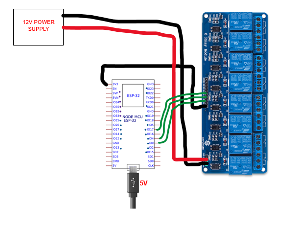
Unlike from the first diagram, the arduino is powered with dc power or usb power, so arduino 5v pin outputs 5V. The issue is that I will power my esp32 on its 3.3V pin. Will that be a problem? Should relay's Vcc be directly from esp's 3.3v output? Like from the first diagram.
If the ESP32's GPIO pin draws current from the module's Vcc pin through a resistor, a photodiode, and an indicator LED, then I'm not sure 3.3V would work at all. But 12V would damage the ESP32.
Have you considered changing the buck output to 5V, and powering both the ESP32 and the relay module directly from that?
i just realize this now. so it needs to be a whole separate power supply? if that's the case, should i just use the basic connection? with the jumper attached
I think you shouldn't power an ESP development board with 3.3volt, because some parts on the board might need 5volt. A 5volt cellphone charger with USB lead is an easy way to power an ESP board, and that also will give full opto isolation.
Leo..
Relay diagram here.
There is a ~1.2volt opto diode and a ~1.8volt indicator LED between relay VCC and the ESP pin.
The ESP pin can't receive more than 5volt - 1.2volt - 1.8volt = 2volt from the relay IN pin.
Powering relay VCC with 3.3volt will not drive the opto LED properly.
Leo..
Best to power relay VCC from the 5volt pin of the ESP.
If you power the ESP through USB, then there is about 5volt on that pin.
You can of course also power the ESP with 5volt on the 5volt pin (as well as relay VCC).
But this supply should have no shared ground with relay coil power if you want opto isolation.
Leo..

