HI! I'm making a Halloween decoration that uses relay switches, an ATtiny84, and other small components. I'm supplying the whole circuit with a 12V 2.5A DC adapter, however, I also have a buck step-down converter that steps down the power to 5V for the relay switches and the ATtiny84. I've programmed the relay switches to open and close with a delay in between but for some reason, they open and close at a fast rate which is not how they're programmed to be. Moreover, after a variable amount of activations, the activation doesn't work unless I shut off the power and supply the power once again. I tried using an external 5V 2A power supply for the relay switches alone but that was also problematic (they behaved differently as well). I'm thinking that the way I supply the relay switches or the ATiny84 may be the root of the problem but I'm not entirely sure. Does anyone know what I might be doing wrong? Many thanks! : )
Code:
//#include <SoftwareSerial.h>
//#include <DFRobotDFPlayerMini.h>

// ---- MACROS/PINS ----
#define TRY_ME_BUTTON 0 // 0
#define SENSOR_MODE   1 // 1
#define TRY_ME_MODE   2 // 2
#define SENSOR        3 // 3
#define RX            4 // 4
#define TX            5 // 5
#define CHANNEL_ONE   6 // 6
#define CHANNEL_TWO   7 // 7

// ---- VARIABLES ----
//SoftwareSerial mySoftSerial(TX, RX);
//DFRobotDFPlayerMini myDFMini;

// ---- FUNCTION PROTOTYPES ----
void activationDo();
void armOneMoveDo(byte numTimes, float waitInBetween);
void armTwoMoveDo(byte numTimes, float waitInBetween);
void upDownMoveDo(byte numTimes, float waitInBetween);
void wait(float timeInSeconds);

// ---- FUNCTIONS ----
void setup() {
  pinMode(TRY_ME_MODE  , INPUT_PULLUP);
  pinMode(SENSOR_MODE  , INPUT_PULLUP);
  pinMode(TRY_ME_BUTTON, INPUT_PULLUP);
  pinMode(SENSOR       , INPUT);
  pinMode(CHANNEL_ONE  , OUTPUT);
  pinMode(CHANNEL_TWO  , OUTPUT);

//  mySoftSerial.begin(9600);
//  myDFMini.begin(mySoftSerial);
//  myDFMini.volume(23); // 23

  digitalWrite(CHANNEL_ONE, LOW);
  digitalWrite(CHANNEL_TWO, LOW);
}

void loop() {
  if(!digitalRead(TRY_ME_MODE)){
    if(!digitalRead(TRY_ME_BUTTON)) activationDo();
  }
  else if(!digitalRead(SENSOR_MODE)){
    if(digitalRead(SENSOR)) activationDo();
  }
}

void activationDo(){
//  myDFMini.play(1);

  upDownMoveDo(1, 3);

  for(byte i = 0; i < 2; i++){
    armOneMoveDo(3, 2);
    armTwoMoveDo(3, 3);
    upDownMoveDo(3, 2);
    armTwoMoveDo(4, 2);
    upDownMoveDo(3, 2);
    armOneMoveDo(4, 2);
    upDownMoveDo(2, 3);
  }
}

void armOneMoveDo(byte numTimes, float waitInBetween){
  for(byte i = 0; i < numTimes; i++){
    digitalWrite(CHANNEL_ONE, HIGH);
    wait(waitInBetween);
    digitalWrite(CHANNEL_ONE, LOW);
    wait(waitInBetween);
  }
}

void armTwoMoveDo(byte numTimes, float waitInBetween){
  for(byte i = 0; i < numTimes; i++){
    digitalWrite(CHANNEL_TWO, HIGH);
    wait(waitInBetween);
    digitalWrite(CHANNEL_TWO, LOW);
    wait(waitInBetween);
  }
}

void upDownMoveDo(byte numTimes, float waitInBetween){
  for(byte i = 0; i < numTimes; i++){
    digitalWrite(CHANNEL_ONE, HIGH);
    digitalWrite(CHANNEL_TWO, HIGH);
    wait(waitInBetween);
    digitalWrite(CHANNEL_ONE, LOW);
    digitalWrite(CHANNEL_TWO, LOW);
    wait(waitInBetween);
  }
}

void wait(float timeInSeconds){
  delay(timeInSeconds * 1000);
}
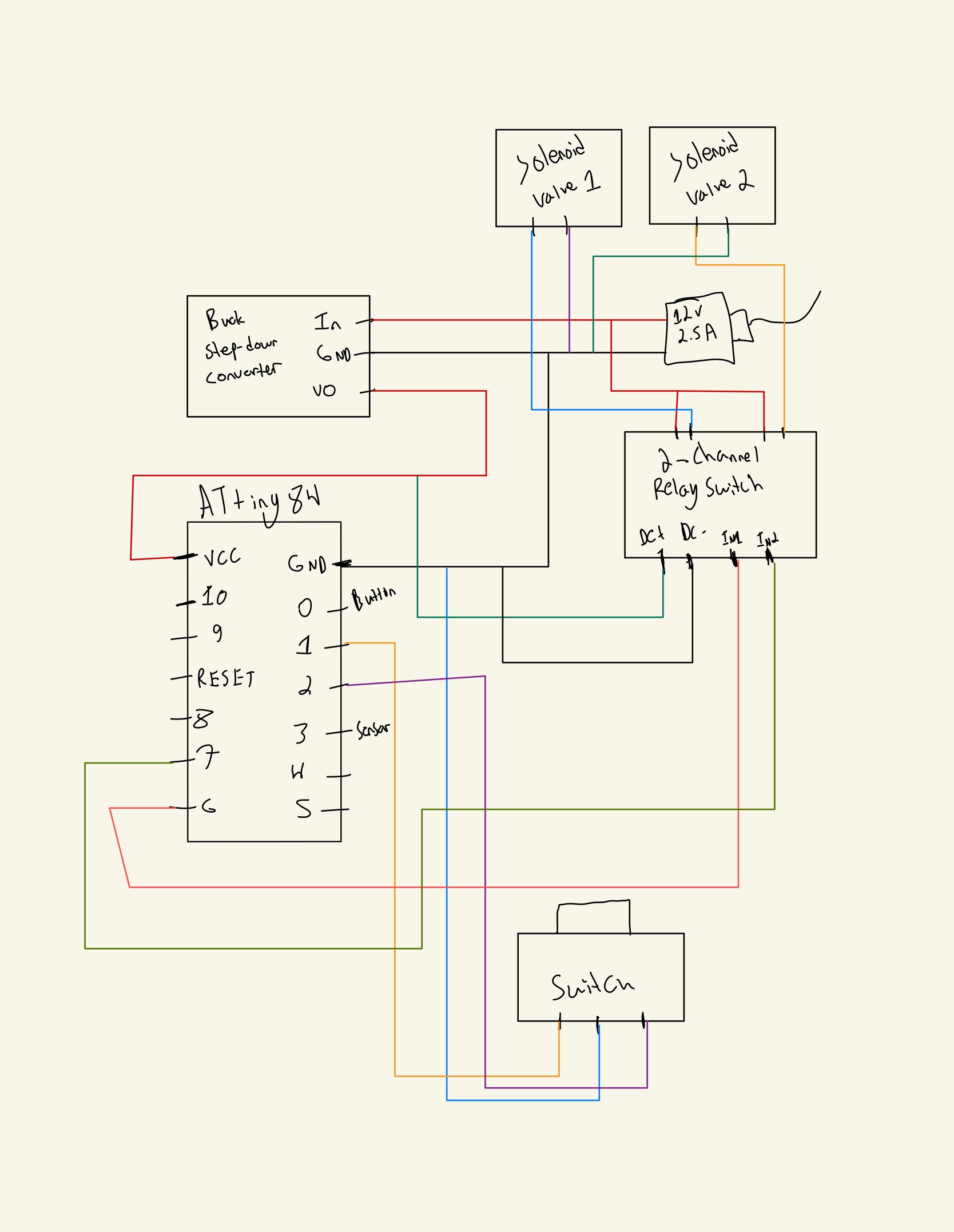
Circuit:
Here's a video of the relay switch using step-down voltage, and here's a video of the relay switch using external 5V 2A voltage.
